Compax3 device description
C3I12T11
192-120113 N08 C3I12T11 - December 2010
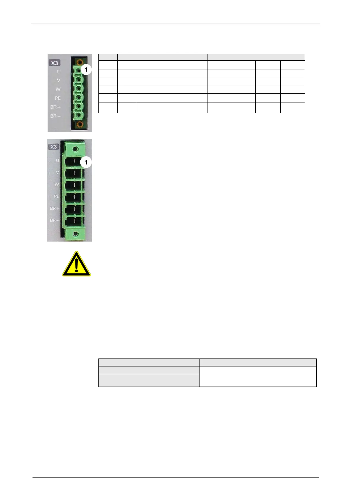
3.3.4. Motor / Motor brake (C3S connector X3)
Motor cable lead designation*
1 U (motor)
U / L1 / C / L+ 1 U1
2 V (motor)
V / L2 2 V2
3 W (motor)
W / L3 / D / L- 3 W3
4 PE (motor)
YE / GN YE / GN YE / GN
5 BR+ Motor holding brake
WH 4 Br1
6 BR- Motor holding brake
BK 5 Br2
* depending on the cable type
Requirements for motor cable
< 100m (the cable should not be rolled up!)
A motor output filter (see on page 336) is required for motor cables >20 m:
Shielding connection of the motor cable
The cable must be fully-screened and connected to the Compax3 housing. Use the
cable clamps/shield connecting terminals furnished with the device.
The shield of the cable must also be connected with the motor housing. The fixing
(via plug or screw in the terminal box) depends on the motor type.
Attention - Please wire the motor holding brake!
Connect the brake only on motors which have a holding brake! Otherwise make no
brake connections at all.
Requirements cables for motor holding brake
If a motor holding brake is present, one cable of the motor holding brake must be
fed on the device side through the toroidal core ferrite provided as accessory
ZBH0x/xx (63Ω @1MHz, di=5.1mm), in order to ensure error-free switching on and
off of the motor holding brake.
Motor holding brake output
Motor holding brake output
Voltage range
21 – 27VDC
Maximum output current (short circuit
proof)
1.6A
Motor cable

 Loading...


