Parker EME
Compax3 device description
192-120113 N08 C3I12T11 - December 2010
3.6.8. Braking resistor / supply voltage C3H
The energy generated during braking operation is absorbed by the Compax3
storage capacity.
If this capacity is too small, the braking energy must be drained via a braking
resistor.
3.6.8.1 Connect braking resistor C3H
Connection of braking resistor - figure (see on page 53)
DBR+ + Braking resistor
DBR- - Braking resistor
Braking operation of Compax3HxxxV4
Capacitance / storable energy
400V / 480V
2600 µF
602 / 419 Ws
3150 µF
729 / 507 Ws
5000 µF
1158 / 806 Ws
5000 µF
1158 / 806 Ws
Minimum braking- resistance
24 Ω 15 Ω 8 Ω 8 Ω
Maximum continuous current
11 A 17 A 31 A 31 A
Minimum line cross section: 2.5mm
2
Maximum line length: 2m
Maximum output voltage: 830VDC
3.6.8.2 Power supply voltage DC C3H
Connection of power voltage DC -figure (see on page 53)
DC+ + DC high voltage supply
DC- - DC high voltage supply
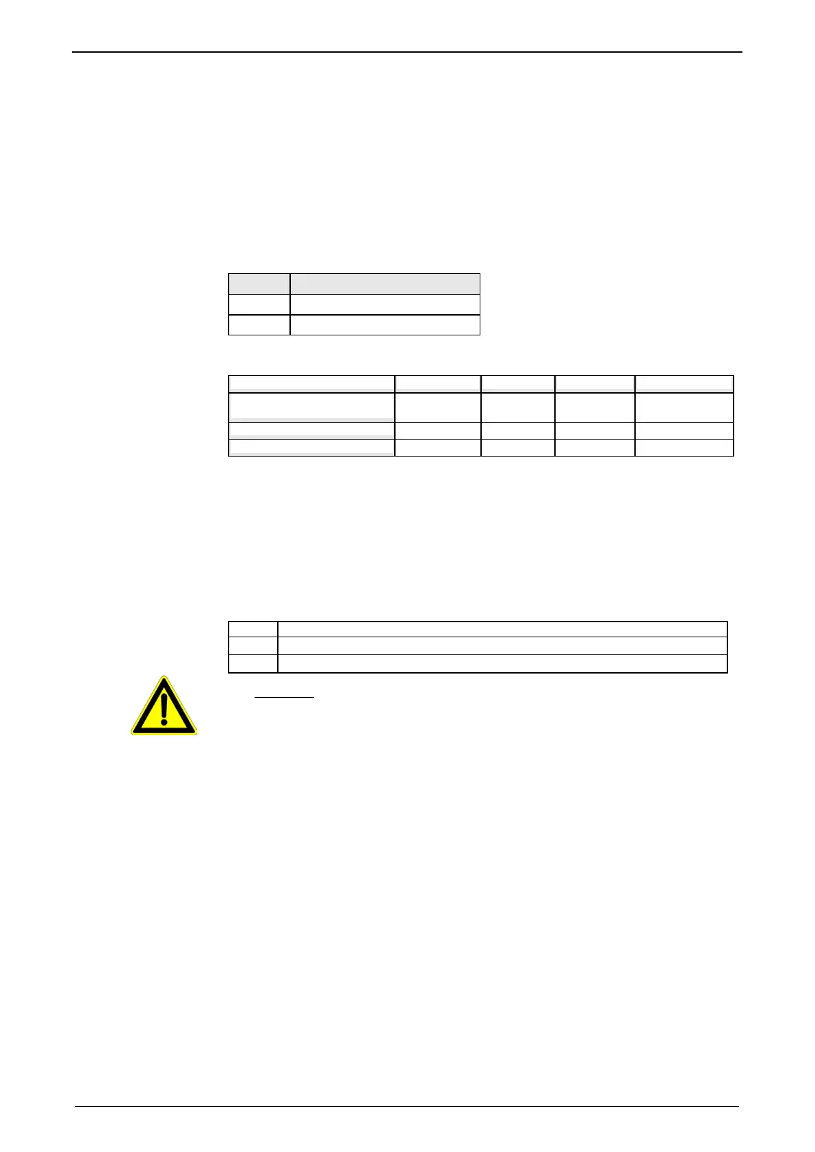
Warning!
Do not connect any braking resistor on DC+/DC- .

 Loading...


