Setting up Compax3
C3I12T11
192-120113 N08 C3I12T11 - December 2010
Standard
In this chapter you can read about:
Standard cascade structure ........................................................................................... 206
Standard optimization parameters ................................................................................. 207
Control signal limitations ................................................................................................ 207
Feedforward channels ................................................................................................... 209
Control signal filter / filter of actual acceleration value .................................................... 211
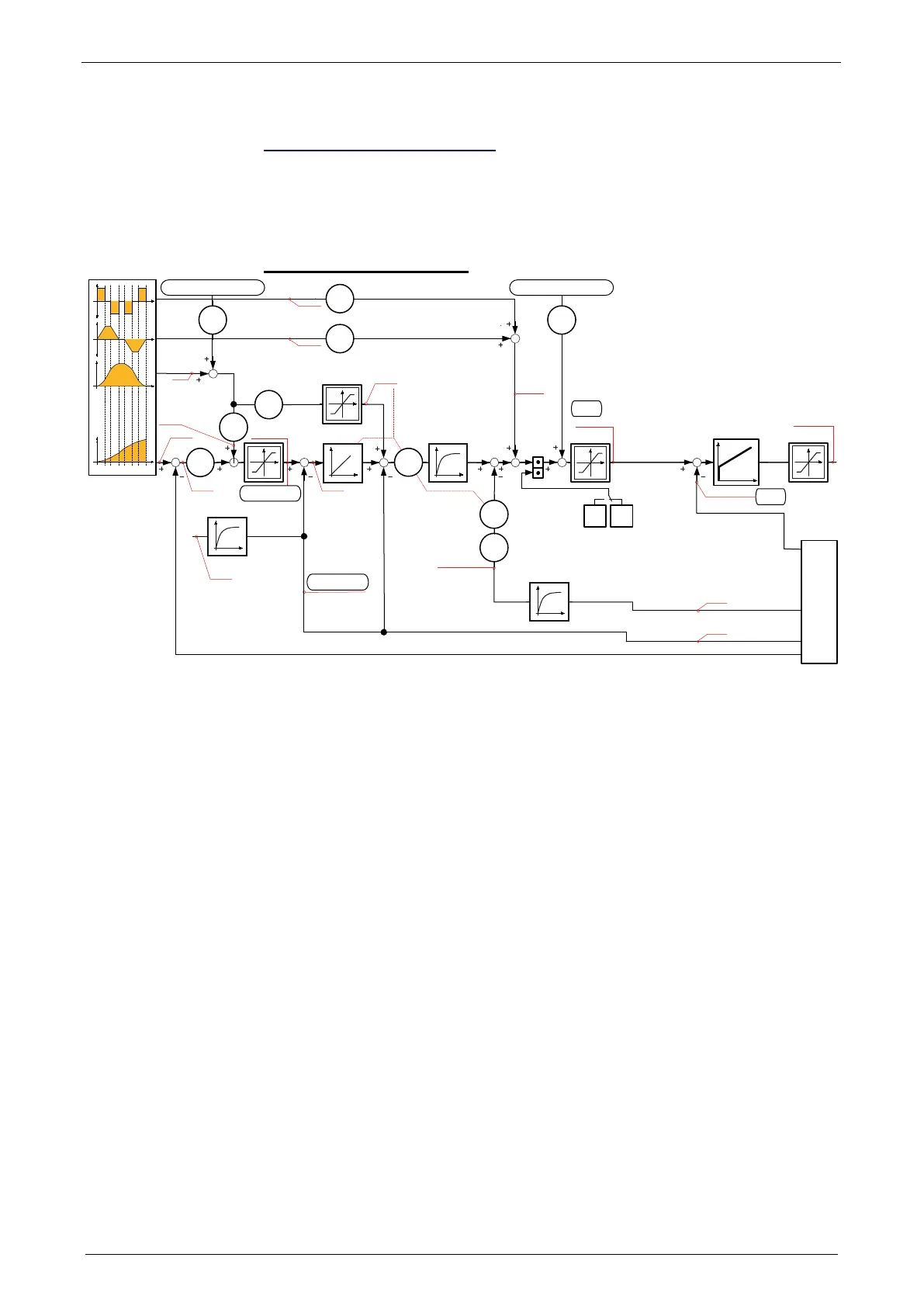
Standard cascade structure
T
K
p
,T
N
T
1
i
mR
*
Synchronous
Motor
Asynchronous
Motor
K
I
682.7
2010.2
688.19
682.6
688.14
681.6
680.6
681.9
681.10
680.4
681.11
681.4
682.4
688.18
688.11
688.13
2010.5
2010.4
2100.2
2100.20
2100.3
2100.4
2100.8
2100.9
2010.1
2100.20
2220.4
2220.1
2220.3
2210
.19
2210.14 2220.2
2210.1
2210.2
T
2100.21
682.5
681.5
Istwerterfassung
Actual Value Monitoring
2100.7
t
t
t
a‘
t
a
v
p
Demand acceleration
Demand jerk
Demand Velocity
Demand position
Velocity
feedforward
Demand
velocity
Following error
actual velocity
filtered
Control deviation
of velocity
Acceleration feedforward
Feedforwaed
current & jerk
demand
current r.m.s.
Voltage control
signal
Actual acceleration
filtered
Manual or external
demant Velocity
Manual or external
demant current
Demand
velocity
actual
velocity
Velocity controller
Stiffness
Damping
Inertia
Current Controller
Bandwidth
Attenuation
Actual current r.m.s.
(torque producing)
Actual velocity
unfiltered
Actual acceleration
unfiltered
The framed objects are coupling objects for Compax3 - Compax3 coupling via
HEDA.
Please note that the corresponding controller components must be deactivated for
the coupling:
When coupling the velocity (O2219.14): O100.1 or O100.2=1063 (see object
description)
When coupling via current (O2220.2): O100.1 or O100.2=1031 (see object
description)
O100.1 is only copied into O100.2 upon activation of the controller, the controller
can be influenced in active state with the aid of O100.2
Changing objects O100.1 and O100.2 may cause the control to be deactivated!
Protect dangerous areas!
External command value
During external setpoint specification, please respect the structure images for
electronic cams or gearboxes for signal filtering with external setpoint
specification (see on page 238) !
Complementary structure for load control (see on page 161).
Compax3 controller structures (see on page 206, see on page 212, see on page
214).

 Loading...


