Parker EME
Compax3 device description
192-120113 N08 C3I12T11 - December 2010
3.6.2. Connection of the power voltage
The terminal block of the drive can be found under the front cover. It is secured
with 2 screws at the bottom of the device. Remove the bottom cover in order to
access the connection clamps.
Make sure that all live parts are covered by the housing after installation.
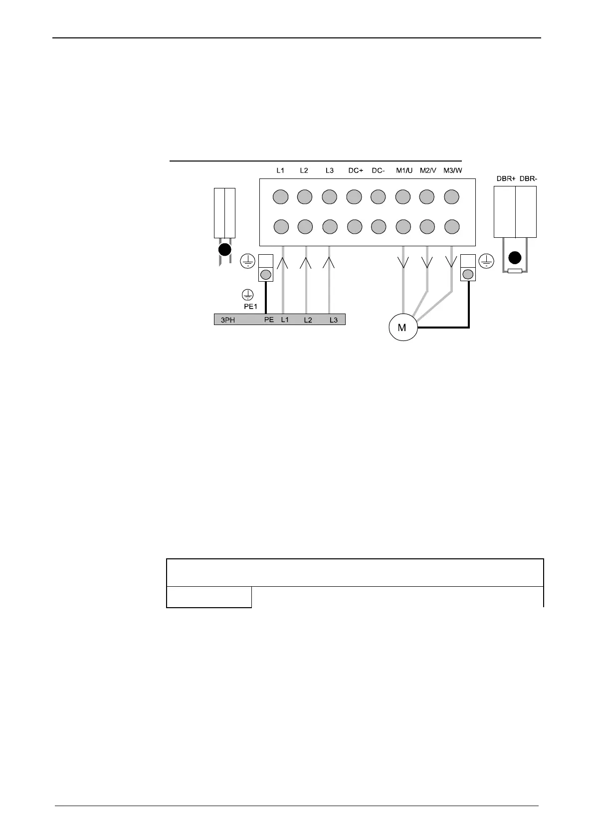
Illustration of the connection clamps exemplarily for all sizes:
L1, L2, L3: 3 phase mains connection
M1, M2, M3: Motor connections
DC+, DC-: DC link voltage
(1) DBR+ und DBR-: Connection of external braking resistor
(2) AUX1, AUX2: only with C3H1xxV4 external supply (AC) for device ventilator L,
N
All shields must be connected via a cable joint to the cable feed through plate.
Braking resistor and cable must be shielded if they are not installed in a control
cabinet.
The standard connection clamps of C3H090V4 and C3H1xxV4 are not suitable
for flat line bars.
Attention: The MOT/TEMP connection is not supported by the Compax3H050; do
therefore not wire this connection!
Terminal clamps - max. line cross sections
The line cross sections must correspond to the locally valid safety regulations. The
local regulations have always priority.
Power clamps
(minimum/maximum section)

 Loading...


