Control via RS232 / RS485 / USB
C3I12T11
192-120113 N08 C3I12T11 - December 2010
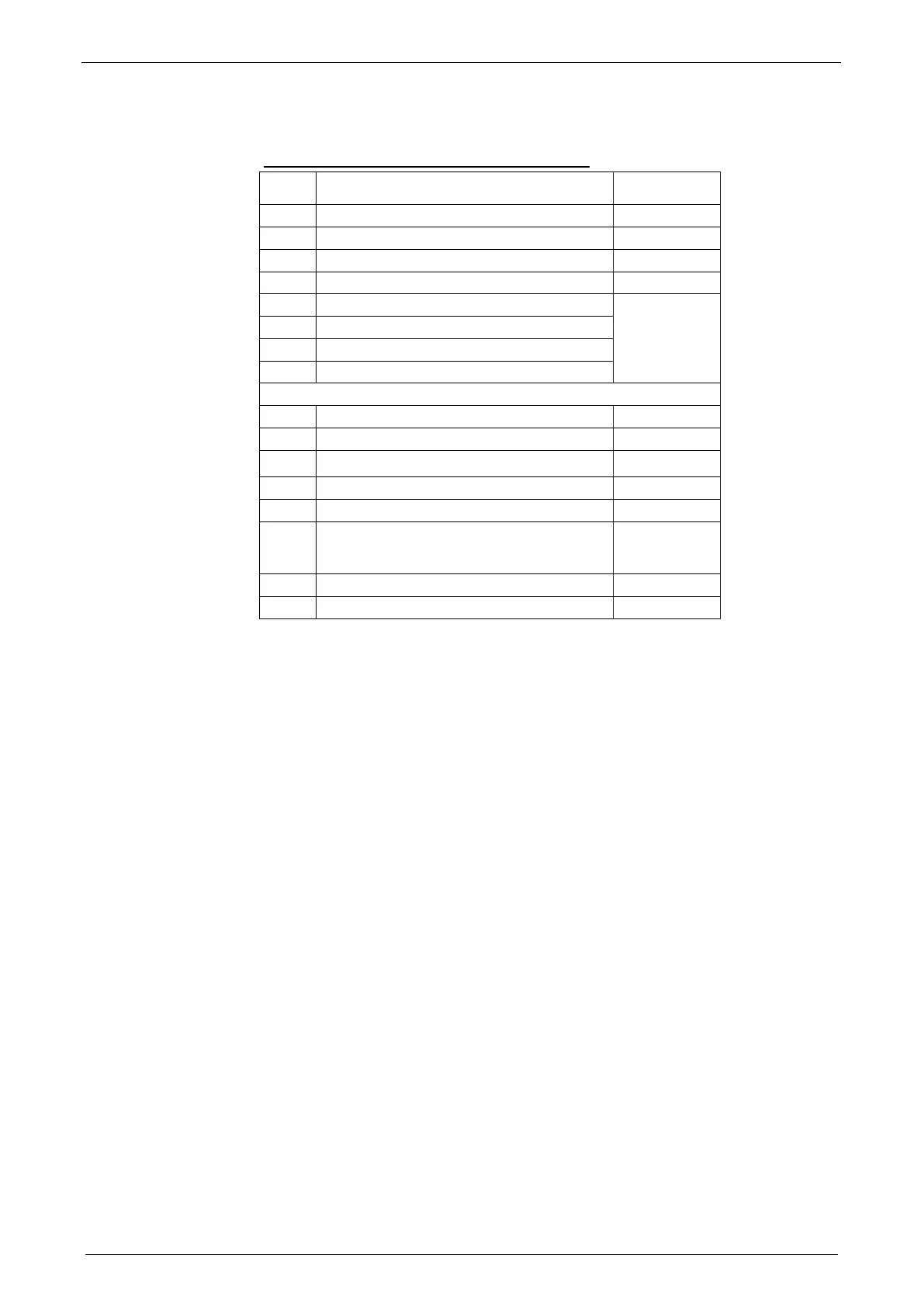
5.2.2. Control word
Structure of the control word (object 1100.3)
Bit0 Quit (edge) / energize axis I0: X12/6
Bit1 No Stop I1: X12/7
Bit2 JOG + I2: X12/8
Bit3 JOG - I3: X12/9
Bit4 O0 X12/2 (only if O0...O3
is defined as
freely
assignable)
Bit5 O1 X12/3
Bit6 O2 X12/4
Bit7 O3 X12/5
Bit8 Address 0
Bit9 Address 1
Bit10 Address 2
Bit11 Address 3
Bit12 Address 4
Bit13 Start (edge)
The address of the current motion set is read
in new.
Bit14 No Stop (2nd Stop)
Bit15 Open brake
* does only apply if the respective inputs are assigned fixedly.
Bit0 = least significant Bit

 Loading...


