3
3.81
9924874 R02 - 2014 RZR XP / XP 4 1000 Service Manual
© Copyright 2013 Polaris Industries Inc.
Important
DO NOT use the “V” mark located on the flywheel opposite of the “I” mark. Only the “I” mark should be used as a TDC
reference
Valve Clearance Adjustment
NOTE: Always inspect valve clearance prior to
camshaft installation or final engine assembly.
1. Reference the camshaft intake and exhaust
markings made during disassembly. If installing new
camshafts or if camshafts were not marked, you can
reference the part number stamped on the end of the
shafts.
Intake Camshaft - PN 1204784
Exhaust Camshaft - PN 1204786
2. Lubricate the camshaft bearing journal surfaces with
Polaris PS-4 engine oil prior to installation.
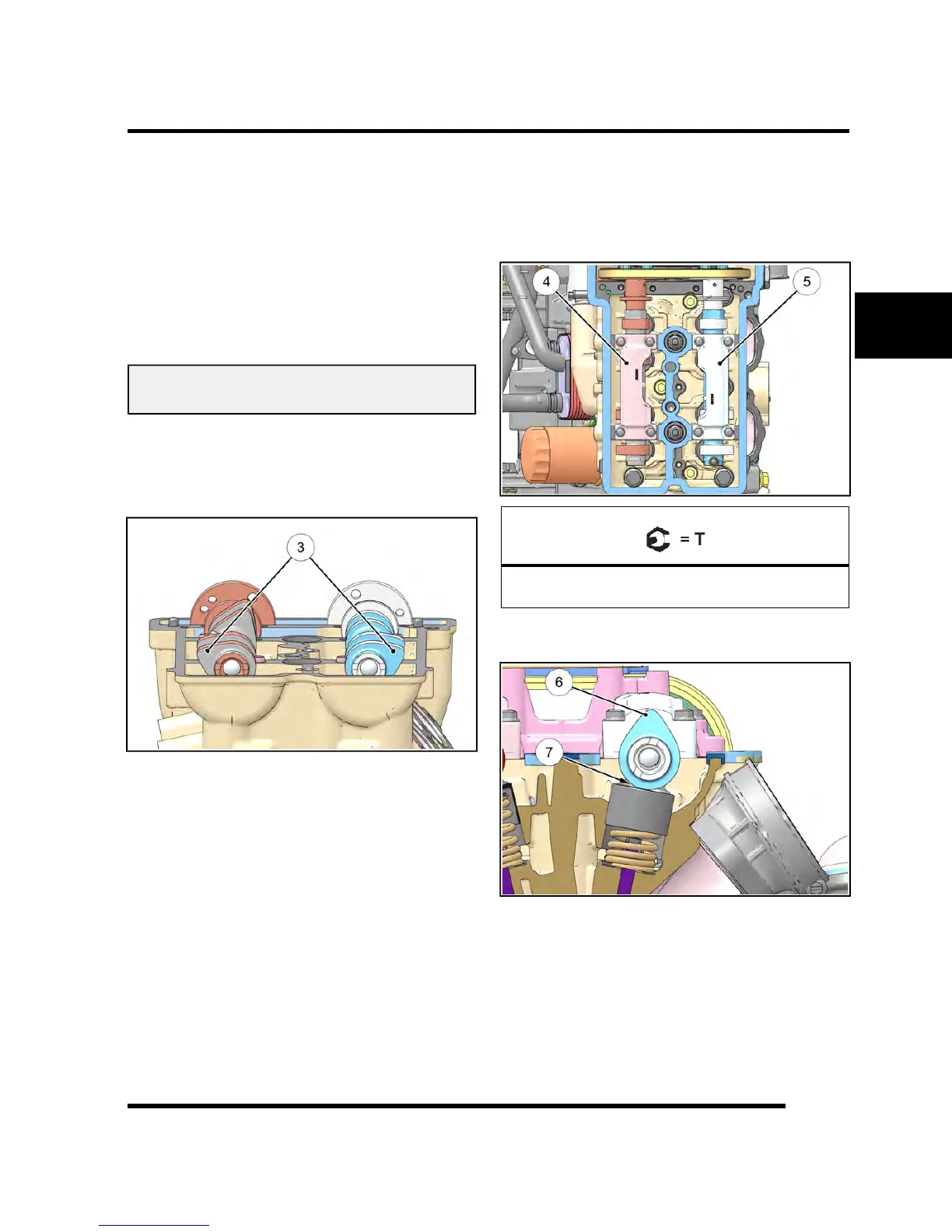
3. Carefully install the camshafts into the cylinder head.
The PTO camshaft lobes (Item 3) should face out as
shown.
4. Carefully install the rear camshaft carriers onto the
camshafts. Carrier openings should face each other
when installed properly.
5. Install the four bolts that retain each rear camshaft
carrier (Item 4 & 5) and tighten the bolts evenly to
specification.
Camshaft Carrier Bolts:
7 ft-lb (10 Nm)
6. Rotate the camshaft until the cam lobes above the
valves you are inspecting are facing up (Item 6).
7. Measure the valve clearance (Item 7) using a
thickness (feeler) gauge. Record the measurement if
clearance is out of specification.
ENGINE

 Loading...