10
10.37
9924874 R02 - 2014 RZR XP / XP 4 1000 Service Manual
© Copyright 2013 Polaris Industries Inc.
Starter Motor Removal
1. Remove driver side seat and disconnect the battery.
2. Raise and support rear of vehicle.
3. Remove the RH rear wheel.
4. Remove (+) positive wire from starter motor terminal.
5. From the RH side wheel well using an 8mm flex
socket, remove the negative battery cable nut and
the (2) fasteners securing the starter motor to the
engine.
NOTE: The (-) negative battery cable is mounted
to the engine using the upper starter mounting
bolt / stud.
6. Remove the starter from the engine.
Starter Motor Installation
1. Inspect and replace starter motor O-ring if needed.
2. Lubricate starter motor O-ring with fresh engine oil.
3. Install the starter motor onto the engine case.
4. Hand tighten the upper starter mounting bolt / stud.
5. Install and torque the lower mounting bolt to
specification.
NOTE: Tighten the lower starter bolt first, as the
bottom hole acts as a pilot hole to properly align
the starter drive (bendix) with the flywheel. This
helps prevent binding and starter damage.
6. Torque upper starter mounting screw to specification.
7. Install (-) negative battery cable to the upper starter
mounting bolt / stud. Torque nut to specification.
Starter Mounting Bolts and Nut:
7 ft-lb (10 Nm)
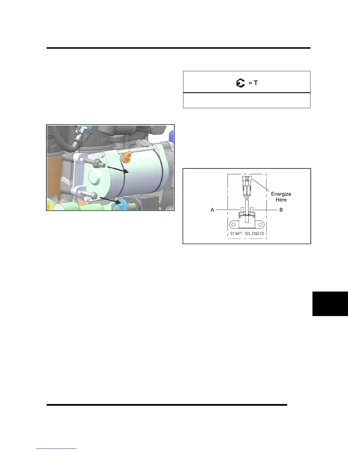
Starter Solenoid Bench Test
Test the start solenoid by powering the solenoid using
battery voltage for a maximum of 5 seconds. With the
solenoid energized, resistance should read about 0 - 0.5
ohms between terminals (A) and (B). If resistance
measurement is out of specification, replace the starter
solenoid.
Starter Solenoid Operation
To energize the Starter Solenoid the following must
occur:
• The brake must be applied to provide a ground
path via the Orange wire.
• The key switch must be turned to the “start”
position to provide 12V power via the Green /
White wire.
• Once the pull-in coil is energized, the solenoid
provides a current path for 12V power to reach the
starter motor.
NOTE: See “ELECTRICAL SYSTEM
BREAOUTS: Starter-Interlock” provided in this
chapter for starter solenoid operation.
ELECTRICAL

 Loading...