RL78/F13, F14 CHAPTER 2 PIN FUNCTIONS
R01UH0368EJ0210 Rev.2.10 72
Dec 10, 2015
(f) INTP13
This is an external interrupt request input pin for which the valid edge (rising edge, falling edge, or both rising and
falling edges) can be specified. This pin is provided only in the 100-pin products of RL78/F14.
(g) SNZOUT2
This is a SNOOZE status output pin.
(h) LTXD0
This is a serial data output pin for the LIN.
(i) LRXD0
This is a serial data input pin for the LIN.
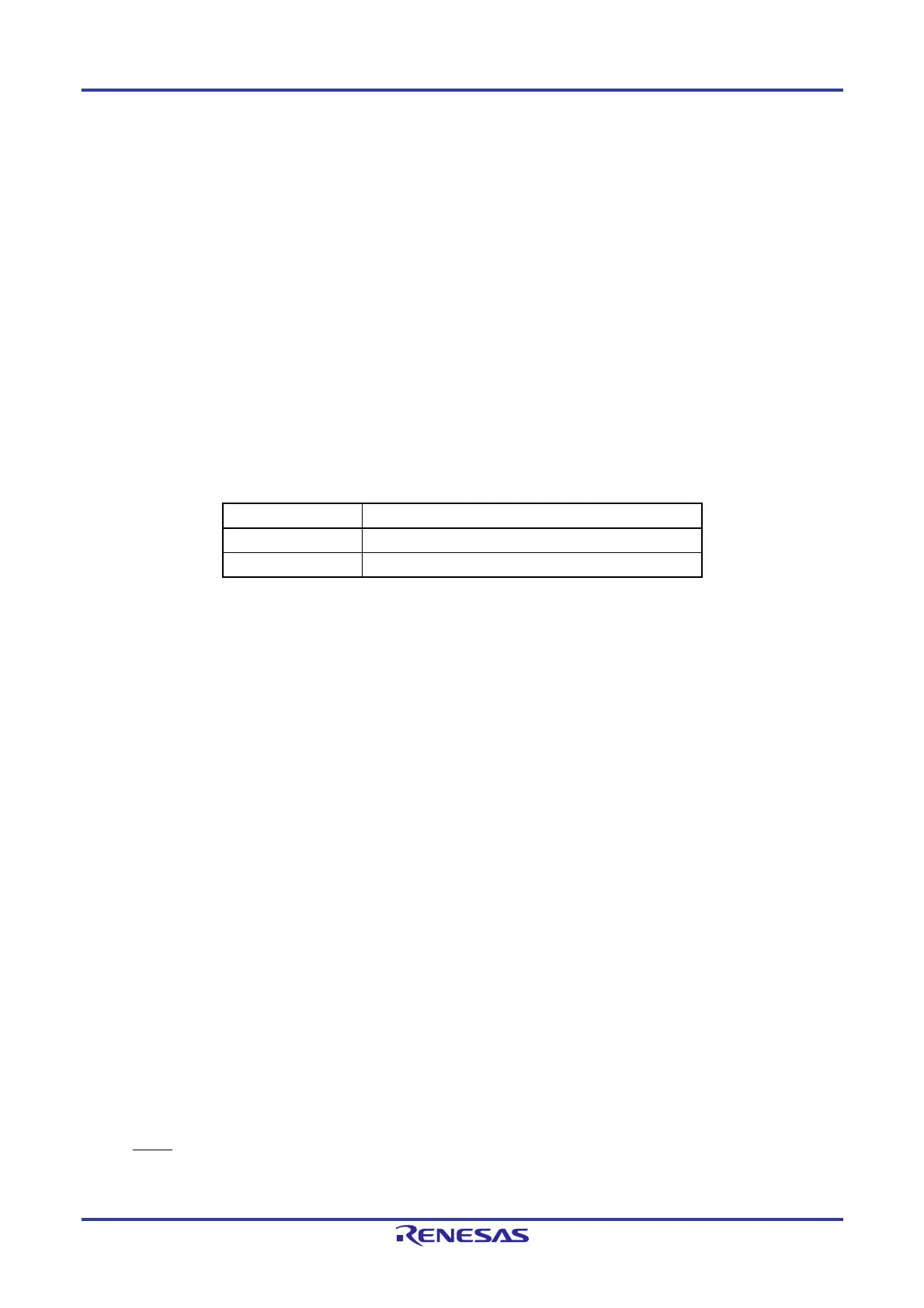
Caution After reset release, the relationships between P40/TOOL0 and the operating mode are as follows. For
details, see 30. 5 Programming Method.
Table 2-5. Relationships Between P40/TOOL0 and Operation Mode After Reset Release
P40/TOOL0 Operating Mode
EVDD Normal operation mode
0 V Flash memory programming mode
2.2.5 P50 to P57 (Port 5)
P50 to P57 function as an I/O port. These pins also function as external interrupt request input, serial interface slave
select input, serial interface data I/O, clock I/O, timer I/O, SNOOZE status output, and STOP status output.
Use of an on-chip pull-up resistor can be specified by pull-up resistor option register 5 (PU5).
For input to the P54 pin, a CMOS input buffer or a TTL input buffer can be selected using the port input mode register 5
(PIM5).
For the P50 and P52 to P54 pins, the input threshold level can be specified using the port input threshold control register
5 (PITHL5).
The following operation modes can be specified in 1-bit units.
(1) Port mode
P50 to P57 function as an I/O port. These pins can be set to input or output port in 1-bit units using port mode register 5
(PM5).
(2) Control mode
P50 to P57 function as external interrupt request input, serial interface slave select input, serial interface data I/O, clock
I/O, timer I/O, SNOOZE status output, and STOP status output.
(a) INTP3, INTP10, INTP11
These are external interrupt request input pins for which the valid edge (rising edge, falling edge, or both rising and
falling edges) can be specified.
(b) SSI01
This is a slave select pin of the CSI01 (SPI01) serial interface.
(c) SSI10
This is a slave select pin of the CSI10 (SPI10) serial interface.

 Loading...


