RL78/F13, F14 CHAPTER 19 DTC
R01UH0368EJ0210 Rev.2.10 1451
Dec 10, 2015
19.3.2 Normal Mode
One to 256 bytes of data are transferred by one activation during 8-bit transfer and 2 to 512 bytes during 16-bit transfer.
The number of transfers can be 1 to 256 times. When the data transfer causing the DTCCTj (j = 0 to 23) register value to
change to 0 is performed, the DTC generates an interrupt request corresponding to the activation source to the interrupt
controller during DTC operation, and sets the corresponding bit among bits DTCENi0 to DTCENi7 (i = 0 to 5
Note
) in the
DTCENi register to 0 (activation disabled).
Table 19-7 shows register functions in normal mode. Figure 19-21 shows data transfers in normal mode.
Note Products of groups A, B, C, and D: i = 0 to 4
Products of group E: i = 0 to 5
Table 19-7. Register Functions in Normal Mode
Register Name Symbol Function
DTC block size register j DTBLSj Size of the data block to be transferred by one activation
DTC transfer count register j DTCCTj Number of data transfers
DTC transfer count reload register j DTRLDj Not used
Note
DTC source address register j DTSARj Data transfer source address
DTC destination address register j DTDARj Data transfer destination address
Note Initialize DTRLDj register with any desired value because the control data are read.
Remark j = 0 to 23
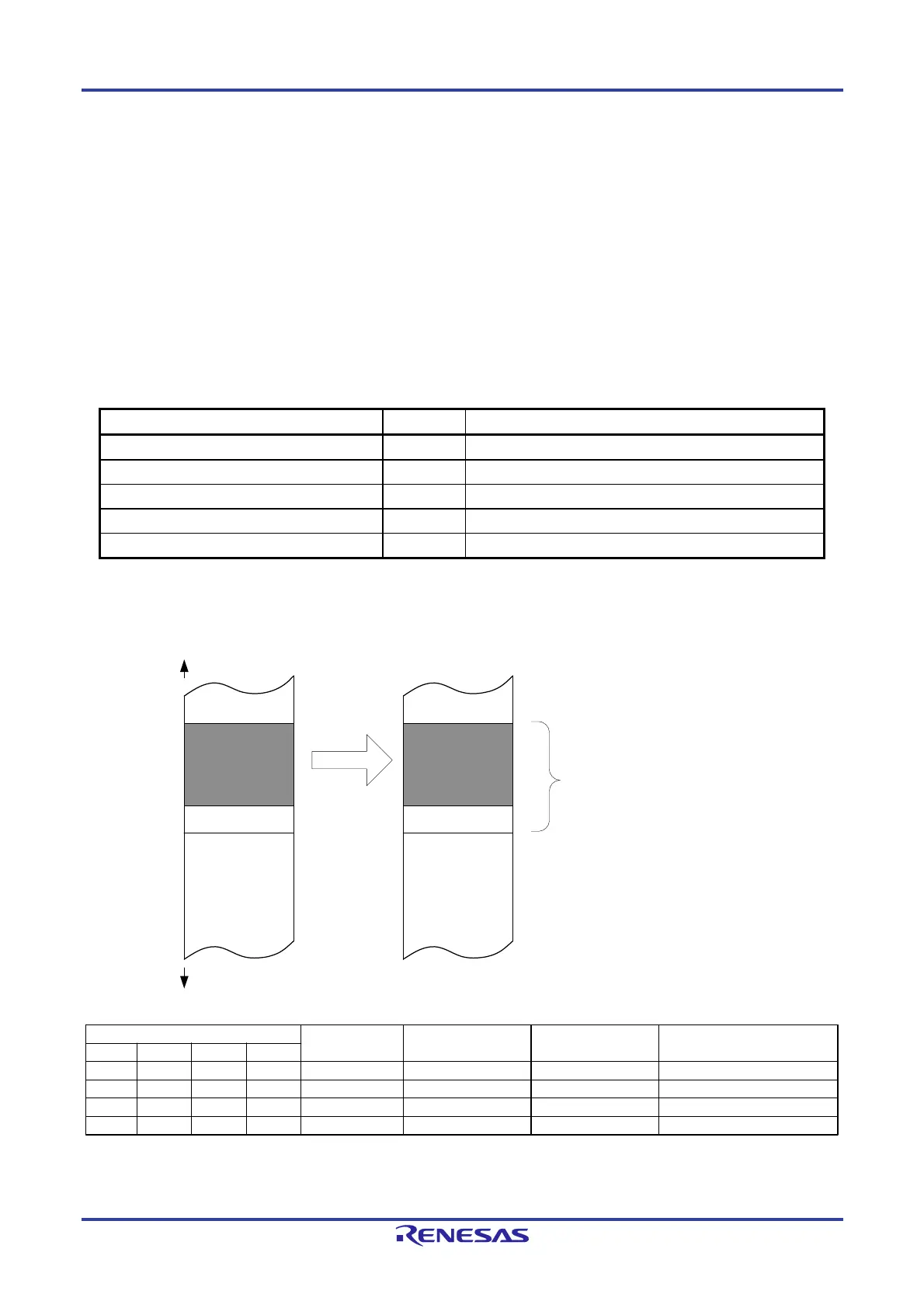
Figure 19-21. Data Transfers in Normal Mode
FFFFFH
SRC
F0000H
Transfer
DST
Size of the data block to be transferred
by one activation
(N bytes)
DTBLSj register = N
DTSARj register = SRC
DTDARj register = DST
j = 0 to 23
DTCCR Register Setting
Source Address
Control
Destination Address
Control
Source Address
after Transfer
Destination Address
after Transfer
DAMOD
SAMOD RPTSEL MODE
0 0 X 0 Fixed Fixed SRC DST
0 1 X 0 Incremented Fixed SRC + N DST
1 0 X 0 Fixed Incremented SRC DST + N
1 1 X 0 Incremented Incremented SRC + N DST + N
X: 0 or 1

 Loading...


