RL78/F13, F14 CHAPTER 19 DTC
R01UH0368EJ0210 Rev.2.10 1450
Dec 10, 2015
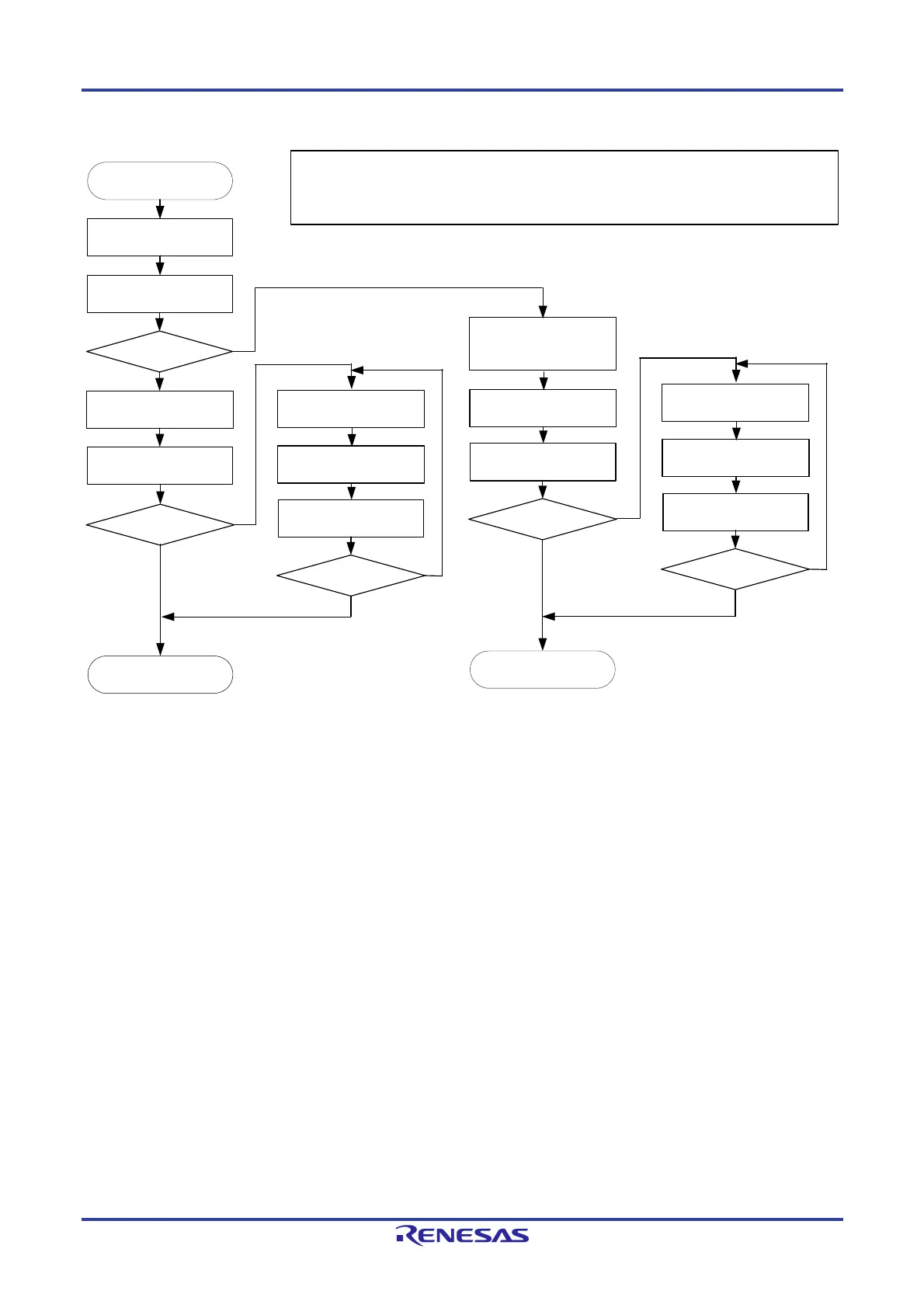
Figure 19-20. DTC Internal Operation Flowchart
Transfer data
Branch (1)
Yes
Read control data
Read DTC vector
DTC activation source
generation
Write back
control data
CHNE = 1?
No
Yes
No
Read control data
Transfer data
Write back
control data
CHNE = 1?
Write 0 to the bit among bits
DTCENi0 to DTCENi7
Generate an interrupt
request
Transfer data
Write back
control data
CHNE = 1?
Yes
No
Yes
Read control data
Transfer data
Write back
control data
CHNE = 1?
Yes
No
No
(Note 1)
End
Interrupt handling
Notes 1. 0 is not written to the bit among bits DTCENi0 to DTCENi7 for data transfers activated by the setting to enable
chain transfers (the CHNE bit is 1). Also, no interrupt request is generated.
2. Products of groups A, B, C, and D: i = 0 to 4
Products of group E: i = 0 to 5
Branch (1)
0 is written to the bit among bits DTCENi0 to DTCENi7 and an interrupt request is generated when transfer is
either of the following:
- A transfer that causes the DTCCTj (j = 0 to 23) register value to change from 1 to 0 in normal mode
- A transfer that causes the DTCCTj register value to change from 1 to 0 while the RPTINT bit is 1 in repeat mode
Remark:
DTCENi0 to DTCENi7: Bits in DTCENi (i = 0 to 5
Note 2
) register
RPTINT, CHNE: Bits in DTCCRj (j = 0 to 23) register

 Loading...


