RL78/F13, F14 CHAPTER 14 COMPARATOR (RL78/F14 Only)
R01UH0368EJ0210 Rev.2.10 776
Dec 10, 2015
CHAPTER 14 COMPARATOR (RL78/F14 Only)
14.1 Overview
The comparator compares a reference voltage to an analog input voltage. The results of a comparison of reference
voltage and analog input voltage can be read by software. The comparison result is output externally and an interrupt or
ELC event is requested upon detection of a change between the two voltages.
The reference input voltage can be either the input from the IVREF0 pin or the output from the on-chip D/A converter.
There are four analog input pins, one of which is to be selected.
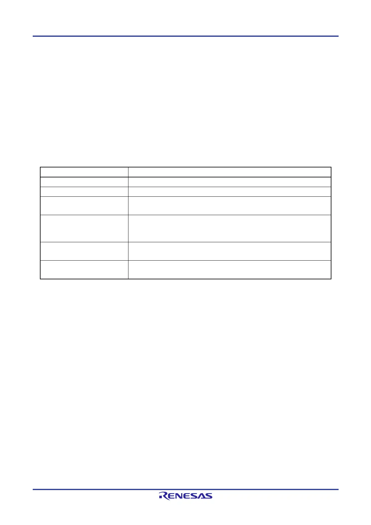
Table 14-1 lists the comparator specifications and figure 14-1 shows the Comparator Block Diagram.
Table 14-1. Comparator Specifications
Item Specification
Number of channels One (comparator 0)
Analog input voltage Input voltage from the IVCMP00 to IVCMP03 pins (one of them to be selected)
Reference voltage
Internal reference voltage (output from on-chip D/A converter)
Input voltage from the external reference voltage input pin (IVREF0)
Comparator output
Comparison result
Generation of ELC event output
Monitor output from register
Interrupt request signal An interrupt request is generated on detecting a valid edge of comparison result.
Rising edge, falling edge, or both edges can be selected.
Digital filter function One of three sampling frequencies can be selected.
Not using the filter function can be selected.

 Loading...


