RL78/F13, F14 CHAPTER 18 CAN INTERFACE (RS-CAN LITE)
R01UH0368EJ0210 Rev.2.10 1415
Dec 10, 2015
18.12 Transmission Procedure
18.12.1 Procedure for Transmission from Transmit Buffers
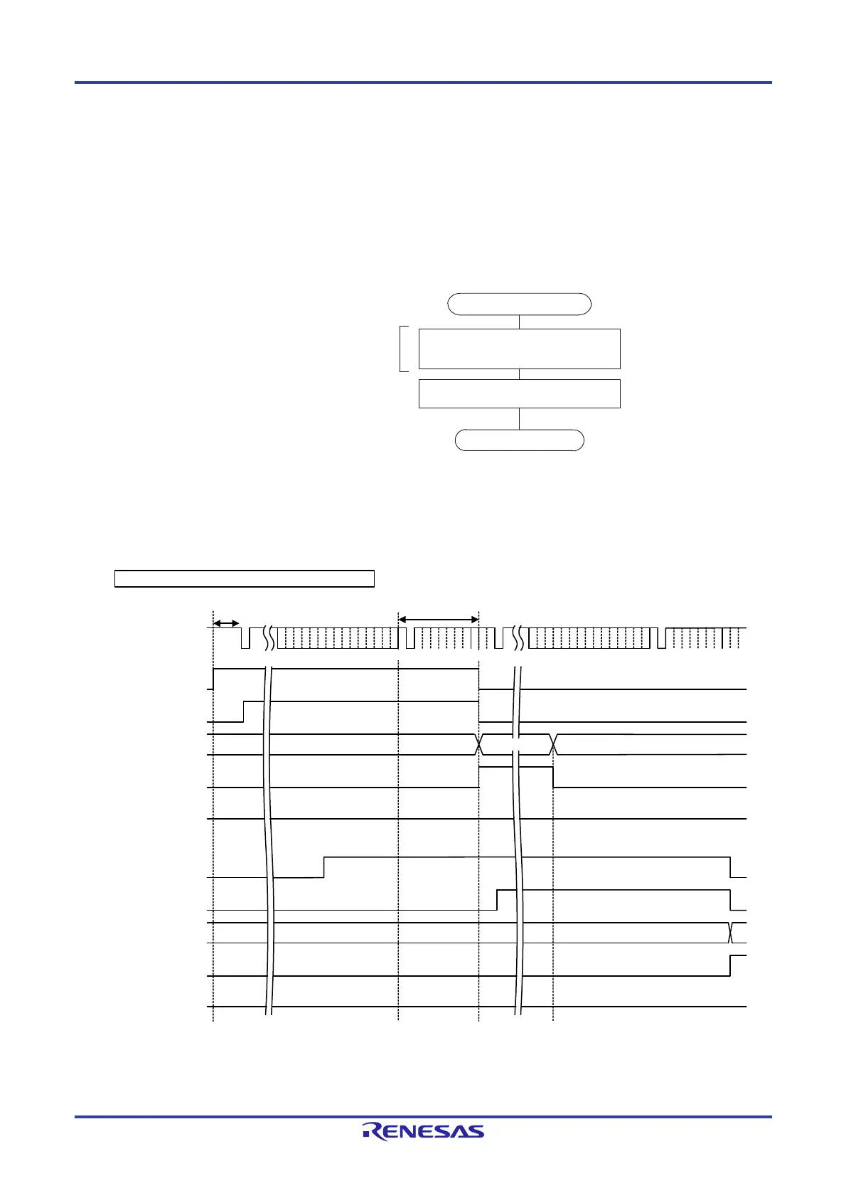
Figure 18-26 shows the procedure for transmission from transmit buffers.
Figure 18-27 shows a timing chart where messages are transmitted from two transmit buffers and transmission has
been successfully completed. Figure 18-28 shows a timing chart where messages are transmitted from two transmit
buffers and transmit abort has been completed.
Figure 18-26. Procedure for Transmission from Transmit Buffers
Figure 18-27. Transmit Buffer Transmission Timing Chart
(Transmission Completed Successfully)
CAN bus
TMTR bit
TMTSTS flag
TMTRF[1:0] flag
TMTCSTSa flag
TMTASTSa flag
TMTR bit
TMTSTS flag
TMTRF[1:0] flag
(1)
(2) (3) (4)
B'10
B'00
B'00
SOF
Determine next
transmit priority
Determine next
transmit priority
EOF
SOF
CRC delimiter EOF
INT
B'00
Remark a = 0 to 3, b = 0 to 3
TMTR: Bit in the TMCa or TMCb register
TMTSTS, TMTRF[1:0]: Flags in the TMSTSa or TMSTSb register
TMTCSTSa, TMTCSTSb: Flag in the TMTCSTS register
TMTASTSa, TMTASTSb: Flag in the TMTASTS register
INTCRC delimiter
H
L
B'10
[Transmit buffer a]
[Transmit buffer b]
Example of transmission from transmit buffers a and b
1
0
1
0
1
0
1
0
1
0
1
0
1
0
1
0
TMTCSTSb flag
TMTASTSb flag
Store messages in transmit buffers
(registers TMIDLp, TMIDHp, TMPTRp, and
TMDF0p to TMDF3p)
Remark p = 0 to 3
Start
Set the TMTR bit in the corresponding TMCp
register to 1 (transmission is requested).
Write messages when the RPAGE bit in
the GRWCR register is set to 1.
End

 Loading...


