RL78/F13, F14 CHAPTER 15 SERIAL ARRAY UNIT
R01UH0368EJ0210 Rev.2.10 796
Dec 10, 2015
15.2 Configuration of Serial Array Unit
The serial array unit includes the following hardware.
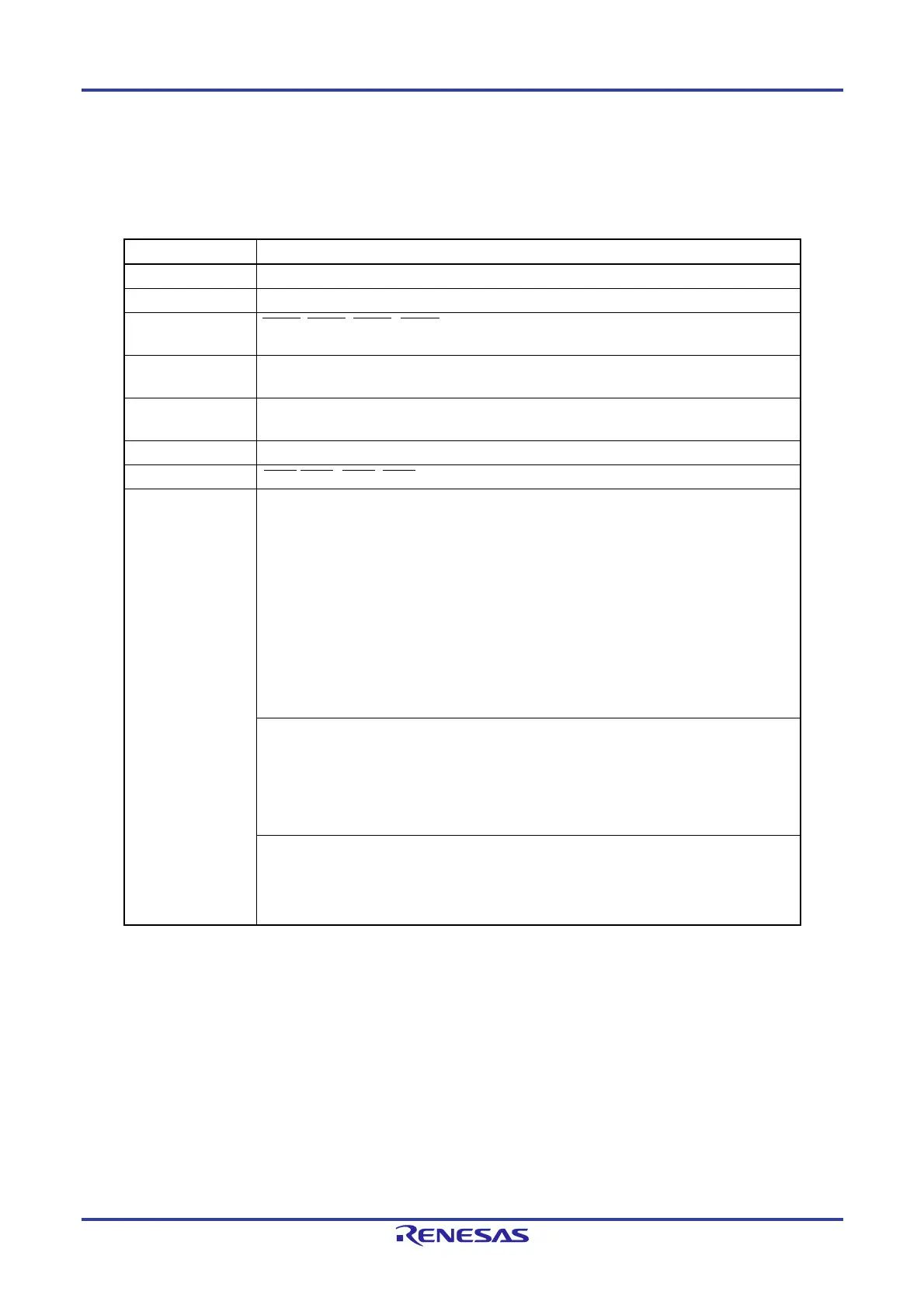
Table 15-1. Configuration of Serial Array Unit
Item Configuration
Shift register 16 bits
Buffer register Serial data register mn (SDRmn)
Note
Serial clock I/O
SCK00, SCK01, SCK10, SCK11 pins (for 3-wire serial I/O), SCL00, SCL01, SCL10, SCL11 pins
(for simplified I
2
C)
Serial data input
SI00, SI01, SI10, SI11 pins (for 3-wire serial I/O), R
XD0 pin (for UART supporting LIN-bus),
RxD1 pin (for UART)
Serial data output
SO00, SO01, SO10, SO11 pins (for 3-wire serial I/O), T
XD0 pin (for UART supporting LIN-bus),
TxD1 pin (for UART), output controller
Serial data I/O
SDA00, SDA01, SDA10, SDA11 pins (for simplified I
2
C)
Slave select input SSI00, SSI01, SSI10, SSI11 pin (for 3-wire serial I/O)
Control registers
<Registers of unit setting block>
• Peripheral enable register 0 (PER0)
• Serial clock select register m (SPSm)
• Serial channel enable status register m (SEm)
• Serial channel start register m (SSm)
• Serial channel stop register m (STm)
• Serial output enable register m (SOEm)
• Serial output register m (SOm)
• Serial output level register m (SOLm)
• Serial slave select enable register m (SSEm)
• Input switch control register (ISC)
• Noise filter enable register 0 (NFEN0)
<Registers of each channel>
• Serial data register mn (SDRmn)
• Serial mode register mn (SMRmn)
• Serial communication operation setting register mn (SCRmn)
• Serial status register mn (SSRmn)
• Serial flag clear trigger register mn (SIRmn)
• Port input mode registers 1, 3, 5 to 7, 12 (PIM1, PIM3, PIM5 to PIM7, PIM12)
• Port output mode registers 1, 6, 7, 12 (POM1, POM6, POM7, POM12)
• Port mode registers 1, 3 to 7, 12 (PM1, PM3 to PM7, PM12)
• Port registers 1, 3 to 7, 12 (P1, P3 to P7, P12)
(Notes and Remark are listed on the next page.)

 Loading...


