RL78/F13, F14 CHAPTER 5 CLOCK GENERATOR
R01UH0368EJ0210 Rev.2.10 395
Dec 10, 2015
5.4 System Clock Oscillator
5.4.1 X1 Oscillator
The X1 oscillator oscillates with a crystal resonator or ceramic resonator (1 to 20 MHz) connected to the X1 and X2 pins.
An external clock can also be input. In this case, input the clock signal to the EXCLK pin.
To use the X1 oscillator, set bits 7 and 6 (EXCLK, OSCSEL) of the clock operation mode control register (CMC) as
follows.
Crystal or ceramic oscillation: EXCLK, OSCSEL = 0, 1
External clock input: EXCLK, OSCSEL = 1, 1
When the X1 oscillator is not used, set the input port mode (EXCLK, OSCSEL = 0, 0).
When the pins are not even used as input port pins, see 2.3 Processing of Unused Pins.
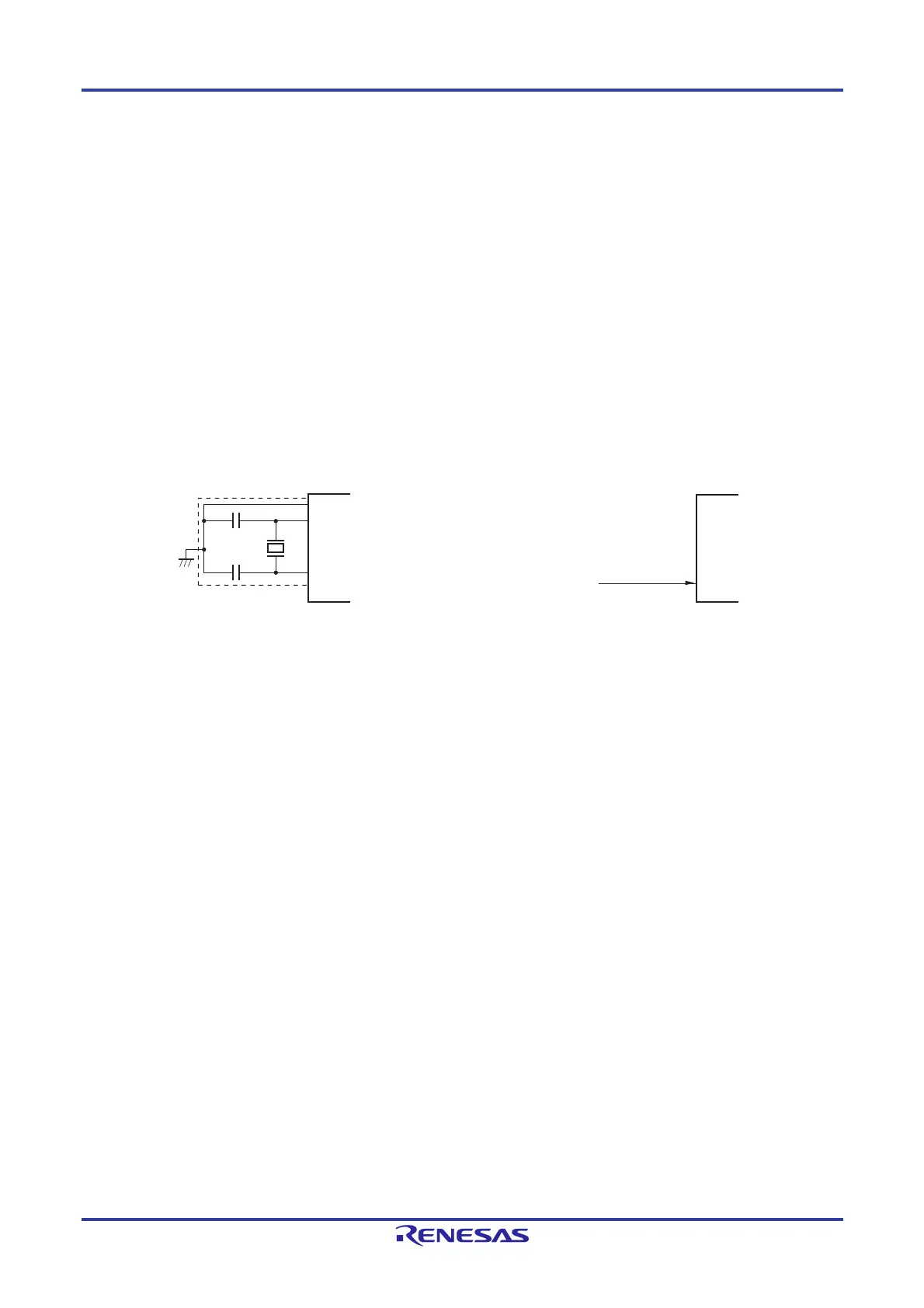
Figure 5-23 shows an example of the external circuit of the X1 oscillator.
Figure 5-23. Example of External Circuit of X1 Oscillator
(a) Crystal or ceramic oscillation (b) External clock
Cautions are listed on the next page.
5.4.2 XT1 Oscillator
The XT1 oscillator oscillates with a crystal resonator (standard: 32.768 kHz) connected to the XT1 and XT2 pins.
To use the XT1 oscillator, set bit 4 (OSCSELS) of the clock operation mode control register (CMC) to 1.
An external clock can also be input. In this case, input the clock signal to the EXCLKS pin.
To use the XT1 oscillator, set bits 5 and 4 (EXCLKS, OSCSELS) of the clock operation mode control register (CMC) as
follows.
Crystal oscillation: EXCLKS, OSCSELS = 0, 1
External clock input: EXCLKS, OSCSELS = 1, 1
When the XT1 oscillator is not used, set the input port mode (EXCLKS, OSCSELS = 0, 0).
When the pins are not even used as input port pins, see 2.3 Processing of Unused Pins.
Figure 5-24 shows an example of the external circuit of the XT1 oscillator.
Crystal resonator
or
ceramic resonator
X1
X2
V
SS
EXCLK
External clock

 Loading...


