RL78/F13, F14 CHAPTER 7 TIMER RJ
R01UH0368EJ0210 Rev.2.10 562
Dec 10, 2015
7.4.6 Pulse Period Measurement Mode
In this mode, the pulse period of an external signal input to the TRJIO0 pin is measured.
The counter is decremented by the count source selected by bits TCK0 to TCK2 in the TRJMR0 register. When a pulse with
the period specified by the TEDGSEL bit in the TRJIOC0 register is input to the TRJIO0 pin, the count value is transferred
to the read-out buffer at the rising edge of the count source. The value in the reload register is loaded to the counter at the
next rising edge. Simultaneously, the TEDGF bit in the TRJCR0 register is set to 1 (active edge received) and an interrupt
request is generated. The read-out buffer (TRJ0 register) is read at this time and the difference from the reload value is the
period data of the input pulse. The period data is retained until the read-out buffer is read. When the counter underflows, the
TUNDF bit in the TRJCR0 register is set to 1 (underflow) and an interrupt request is generated.
Figure 7-17 shows the Operation Example in Pulse Period Measurement Mode.
Only input pulses with a period longer than twice the period of the count source. Also, the low-level and high-level widths
must be both longer than the period of the count source. If a pulse period shorter than these conditions is input, the input
may be ignored.
Caution The 20-pin products do not have TRJIO0 pin. Thus, the pulse period measurement mode cannot be
used.
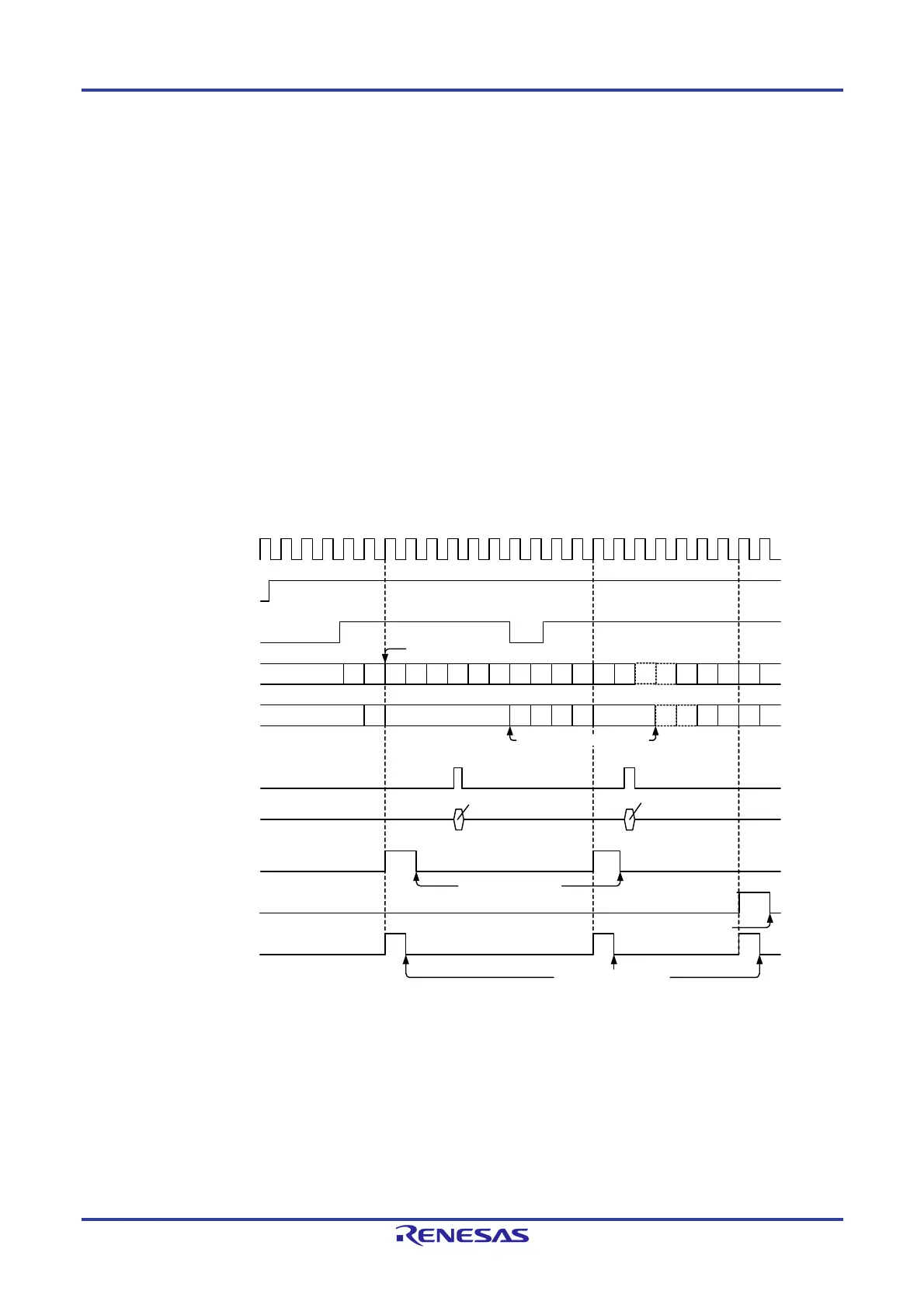
Figure 7-17. Operation Example in Pulse Period Measurement Mode
This example applies when the initial value of the TRJ0 register is set to 0300H, the TEDGSEL bit in the TRJIOC0 register is set to 0, and the
period from one rising edge to the next edge of the measurement pulse is measured.
Notes:
1. Reading from the TRJ0 register must be performed during the period from when the TEDGF bit is set to 1 (active edge received) until the
next active edge is input. The content of the read-out buffer is retained until the TRJ0 register is read. If it is not read before the active
edge is input, the measurement result of the previous period is retained.
2. When the TRJ0 register is read in pulse period measurement mode, the content of the read-out buffer is read.
3. When the active edge of the measurement pulse is input and then the set edge of an external pulse is input, the TEDGF bit in the
TRJCR0 register is set to 1 (active edge received).
4. To set to 0 by a program, write 0 to the TEDGF bit in the TRJCR0 register using an 8-bit memory manipulation instruction.
5. To set to 0 by a program, write 0 to the TUNDF bit in the TRJCR0 register using an 8-bit memory manipulation instruction.
Count source
TSTART bit
in TRJCR0 register
Measurement pulse input
Timer RJ0 counter
Content of read-out buffer
Read signal of counter
Read data
TEDGF bit in
TRJCR0 register
TUNDF bit in
TRJCR0 register
IF bit in
INTC register
Set to 0 by a program
(Note 5)
Acknowledgement of an
interrupt request
(Note 3) (Note 3)
Set to 0 by a program
(Note 4)
0300H
02FEH02F9H02F8H02F7H02FFH •••• 0001H 0000H 0300H02FFH02FFH02FEH0300H02FFH02FEH
02FDH 02FCH
02FBH02FAH 02FEH
(Note 2) (Note 2)
Counter value is read (Note 1)
Counter is reloaded
0300H
02FFH02FAH02F9H02F8H •••• 0001H 0000H0300H02FFH 02FEH 02FBH 02F7H
••••
••••
02FEH 02F7H

 Loading...


