RL78/F13, F14 CHAPTER 15 SERIAL ARRAY UNIT
R01UH0368EJ0210 Rev.2.10 844
Dec 10, 2015
15.5.2 Master reception
Master reception is an operation wherein this MCU outputs a transfer clock and receives data from other device.
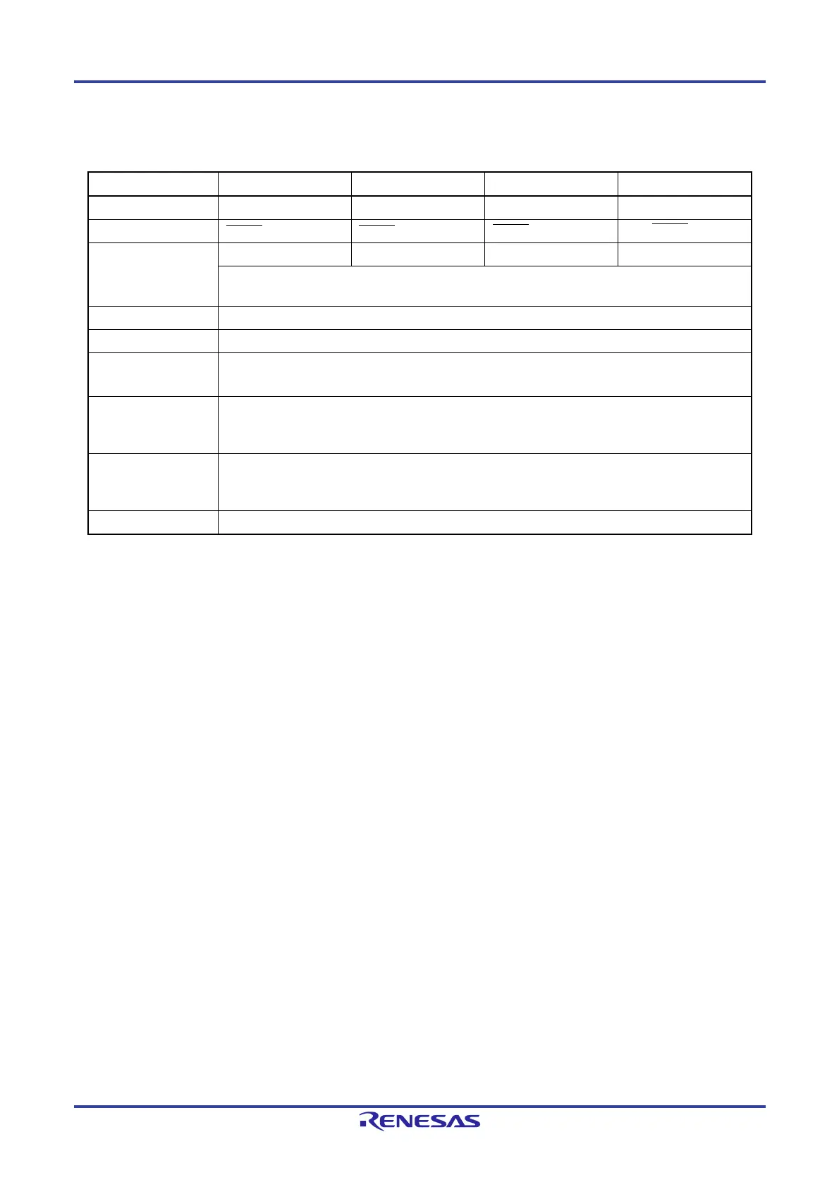
3-Wire Serial I/O CSI00 CSI01 CSI10 CSI11
Target channel Channel 0 of SAU0 Channel 1 of SAU0 Channel 0 of SAU1 Channel 1 of SAU1
Pins used SCK00, SI00 SCK01, SI01 SCK10, SI10 SCK11, SI11
Interrupt INTCSI00 INTCSI01 INTCSI10 INTCSI11
Transfer end interrupt (in single-transfer mode) or buffer empty interrupt (in continuous transfer mode)
can be selected.
Error detection flag Overrun error detection flag (OVFmn) only
Transfer data length 7 to 16 bits
Transfer rate Max. fMCK/4 [Hz]
Min. f
CLK/(2 × 2
11
× 128) [Hz]
Note
fCLK: System clock frequency
Data phase Selectable by the DAPmn bit of the SCRmn register
• DAPmn = 0: Data input starts from the start of the serial clock operation.
• DAPmn = 1: Data input starts half a clock before the start of the serial clock operation.
Clock phase Selectable by the CKPmn bit of the SCRmn register
• CKPmn = 0: Forward
• CKPmn = 1: Reverse
Data direction MSB or LSB first
Note Use this operation within a range that satisfies the conditions above and the AC characteristics in the electrical
specifications.
Remark m: Unit number (m = 0, 1), n: Channel number (n = 0, 1), mn = 00, 01, 10, 11

 Loading...


