RL78/F13, F14 CHAPTER 30 FLASH MEMORY
R01UH0368EJ0210 Rev.2.10 1630
Dec 10, 2015
30.2.2 Communication Mode
Communication between the external device and the RL78/F13 or RL78/F14 is established by serial communication
using the TOOLTxD and TOOLRxD pins via the dedicated UART of the RL78/F13 or RL78/F14.
Transfer rate: 1 M, 500 k, 250 k, 115.2 kbps
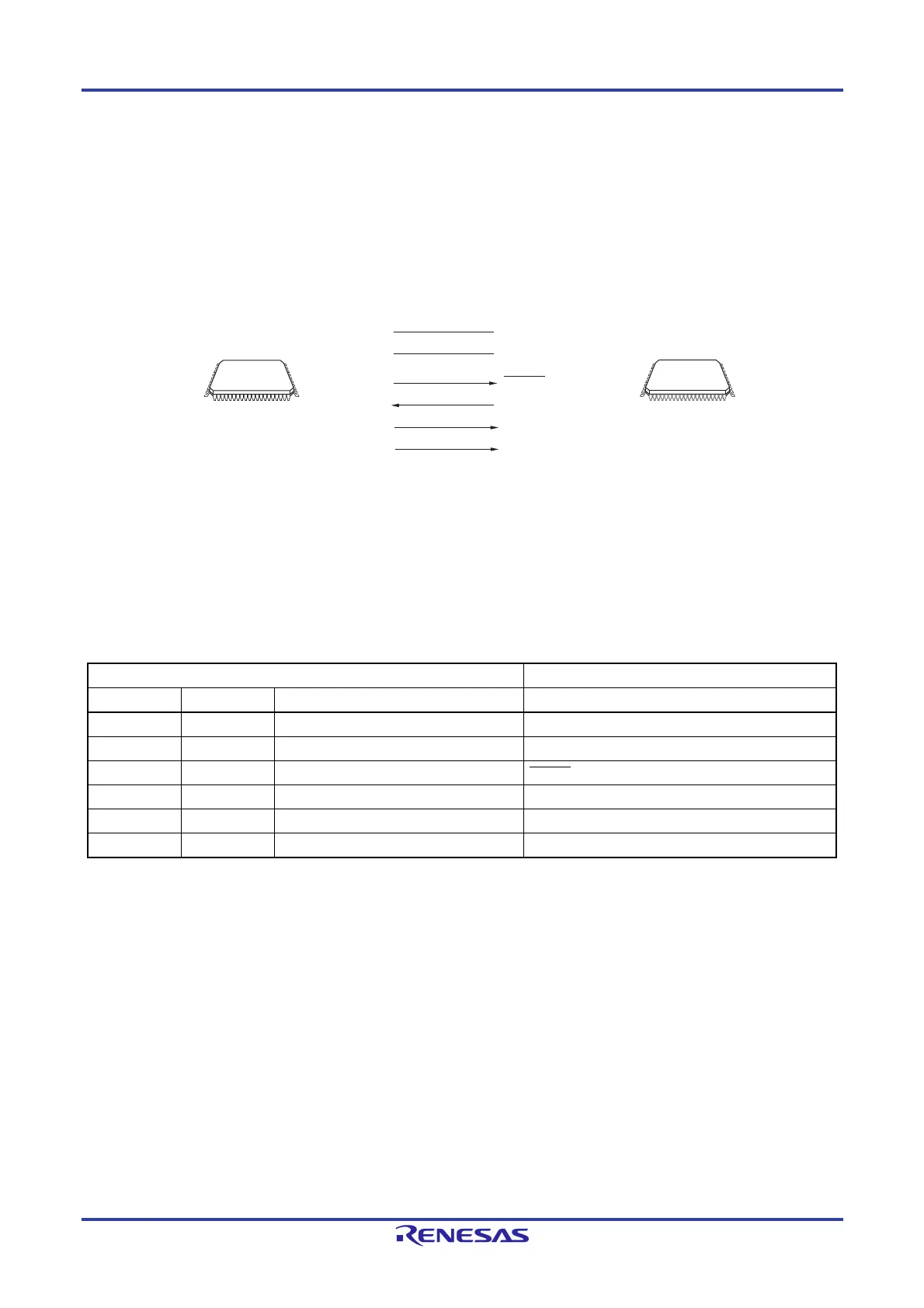
Figure 30-4. Communication with External Device
Notes 1. 64, 80, 100-pin products only.
2. 100-pin products only.
3. Connect REGC pin to ground via a capacitor (0.47 to 1
F).
The external device generates the following signals for the RL78/F13 and RL78/F14.
Table 30-3. Pin Connection
External Device RL78/F13 and RL78/F14
Signal Name I/O Pin Function Pin Name
VDD I/O VDD voltage generation/power monitoring
V
DD, EVDD0
Note 1
, EVDD1
Note 2
GND
Ground
V
SS, EVSS0
Note 1
, EVSS1
Note 2
, REGC
Note 3
RESETOUT Output Reset signal output RESET
RxD Input Receive signal TOOLTxD
TxD Output Transmit signal TOOLRxD
PORT Output Mode signal TOOL0
Notes 1. 64, 80, 100-pin products only.
2. 100-pin products only.
3. Connect REGC pin to ground via a capacitor (0.47 to 1
F).
V
DD
/
EV
DD0
N
o
t
e
1
, EV
DD1
N
o
t
e
2
V
SS
/EV
SS0
N
o
t
e
1
, EV
SS1
N
o
t
e
2
/REGC
N
o
t
e
3
RESET
TOOLTxD
V
DD
GND
/RESET
RL78/F13,
RL78/F14
RxD
TxD
External device
(such as microcontroller
and ASIC)
TOOL0PORT
TOOLRxD

 Loading...


