RL78/F13, F14 CHAPTER 11 WATCHDOG TIMER
R01UH0368EJ0210 Rev.2.10 699
Dec 10, 2015
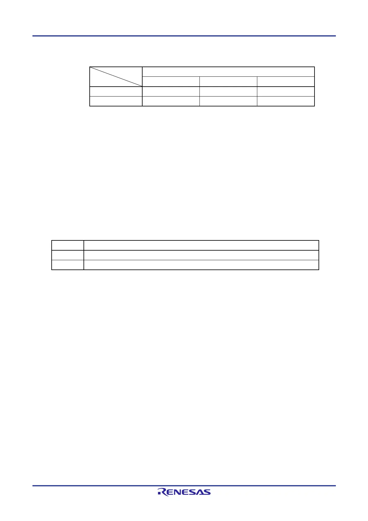
Remark If the overflow time is set to 2
9
/fWDT, the window close time and open time are as follows.
Setting of Window Open Period
50% 75% 100%
Window close time 0 to 20.08 ms 0 to 10.04 ms None
Window open time 20.08 to 29.68 ms 10.04 to 29.68 ms 0 to 29.68 ms
<When window open period is 50%>
Overflow time:
2
9
/fWDT (MAX.) = 2
9
/17.25 kHz (MAX.) = 29.68 ms
Window close time:
0 to 2
9
/fWDT (MIN.) (1 0.5) = 0 to 2
9
/12.75 kHz 0.5 = 0 to 20.08 ms
Window open time:
2
9
/fWDT (MIN.) (1 0.5) to 2
9
/fWDT (MAX.) = 2
9
/12.75 kHz 0.5 to 2
9
/17.25 kHz
= 20.08 to 29.68 ms
11.4.4 Setting watchdog timer interval interrupt
Setting bit 7 (WDTINT) of an option byte (000C0H) can generate an interval interrupt (INTWDTI) when 75% of the
overflow time is reached.
Table 11-5. Setting of Watchdog Timer Interval Interrupt
WDTINT Use of Watchdog Timer Interval Interrupt
0 Interval interrupt is not used.
1 Interval interrupt is generated when 75% of overflow time + 1/2 fWDT is reached.
Caution When operating with the X1 oscillation clock after releasing the STOP mode, the CPU starts
operating after the oscillation stabilization time has elapsed.
Therefore, if the period between the STOP mode release and the watchdog timer overflow is short, an
overflow occurs during the oscillation stabilization time, causing a reset.
Consequently, set the overflow time in consideration of the oscillation stabilization time when
operating with the X1 oscillation clock and when the watchdog timer is to be cleared after the STOP
mode release by an interval interrupt.
Remark The watchdog timer continues counting even after INTWDTI is generated (until ACH is written to the watchdog
timer enable register (WDTE)). If ACH is not written to the WDTE register before the overflow time, an internal
reset signal is generated.

 Loading...


