RL78/F13, F14 CHAPTER 17 LIN/UART MODULE (RLIN3)
R01UH0368EJ0210 Rev.2.10 1214
Dec 10, 2015
17.4.4 Wake-up Transmission/Reception
The wake-up transmission/reception can be used in LIN wake-up mode.
(1) Wake-up Transmission
In LIN wake-up mode, setting the RCDS bit in the LDFCn register to 1 (transmission) and the FTS bit in the LTRCn register
to 1 (header reception or wake-up transmission/reception started) causes a wake-up signal to be output from the output pin.
The low width of the wake-up signal should be set using the WUTL[3:0] bits in the LWUPn register. However, when the
LWBR0 bit in the LWBRn register is 1 in LIN master mode, the low width is defined based on fa as the LIN system clock
(f
LIN) regardless of the setting of LCKS bits in the LMDn register. Setting the baud rate to 19200 bps with fa selected and
setting the WUTL[3:0] bits in the LWUPn register to 0100b (5 Tbits) allows 260 s low level width of the signal to be output
in LIN wake-up mode regardless of the setting of LCKS bits in the LMDn register.
If a wake-up low is output without any bit error, the FTC flag in the LSTn register turns 1 (successful response or wake-up
transmission); when the FTCIE bit in the LIEn register is 1 (successful response/wakeup transmission interrupt enabled), an
interrupt request is generated.
If a bit error is detected, wake-up transmission is canceled and the BER flag in the LESTn register is set to 1 (bit error
detection).
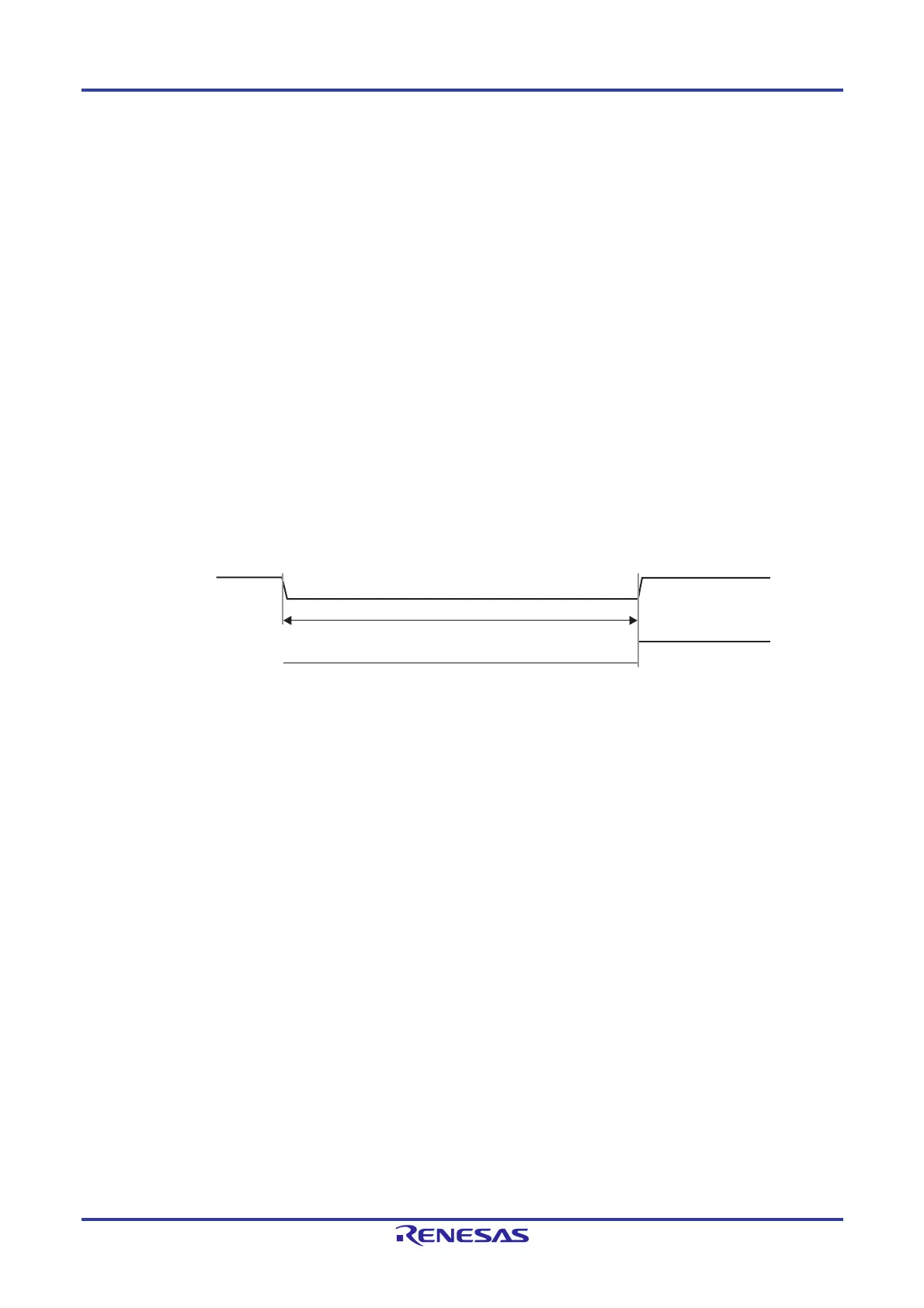
Figure 17-18 shows the wake-up transmission timing.
Figure 17-18. Wake-up Transmission Timing
LTX D n
(n = 0, 1)
FTC bit in
LSTn register
Low width configuration (1 to 16 Tbits)

 Loading...


