RL78/F13, F14 CHAPTER 8 TIMER RD
R01UH0368EJ0210 Rev.2.10 624
Dec 10, 2015
8.3.2 Input Capture Function
The input capture function measures the external signal width and period. The content of the TRDi register (counter) is
transferred to the TRDGRji register as a trigger of the TRDIOji pin (i = 0 or 1, j = A, B, C, or D) external signal (input capture).
Since this function is enabled with a combination of the TRDIOji pin and TRDGRji register, the input capture function, or any
other mode or function, can be selected for each individual pin.
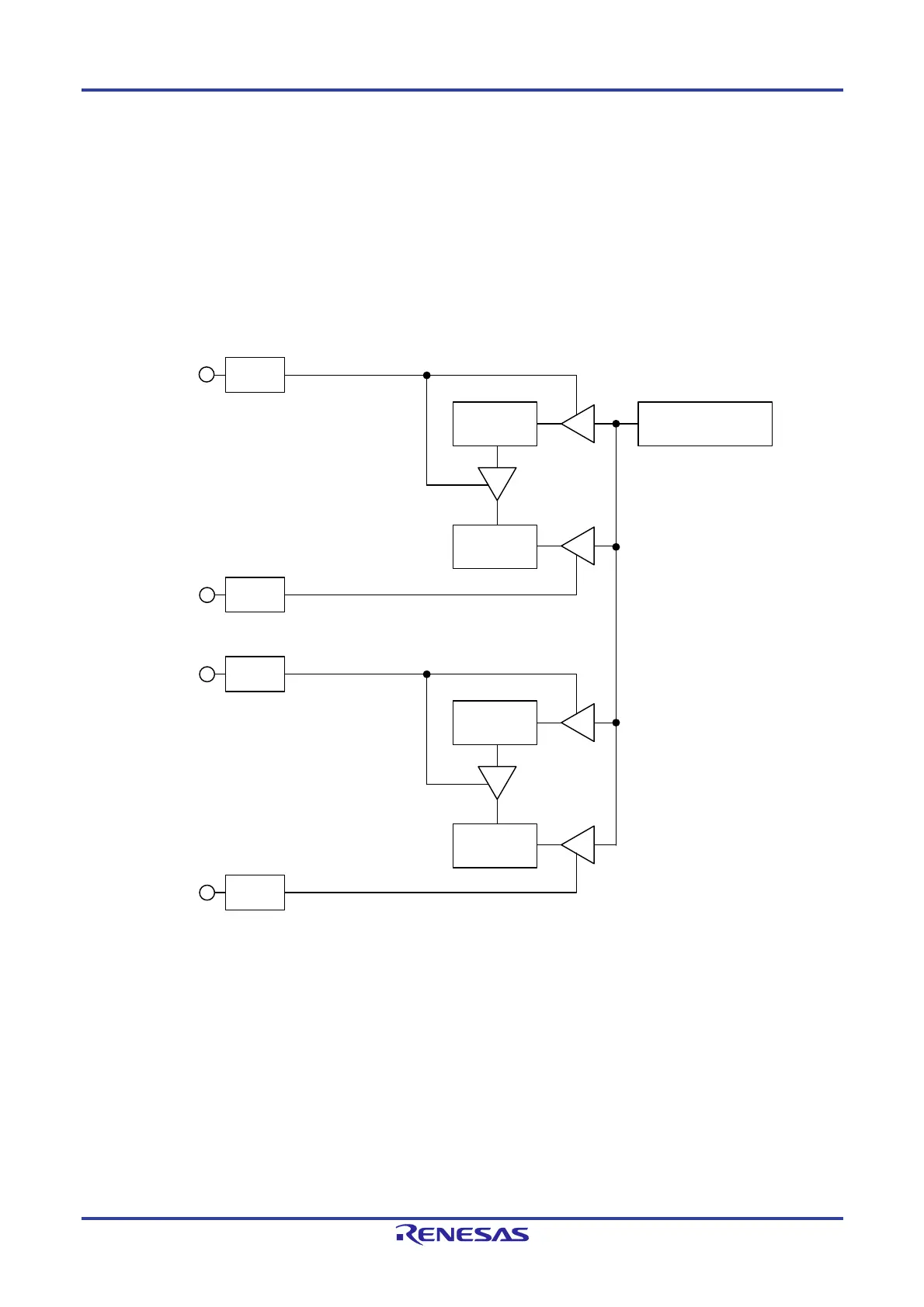
Figure 8-45 shows the Block Diagram of Input Capture Function, Table 8-14 lists the Input Capture Function
Specifications, and Figure 8-46 shows an Operation Example of Input Capture Function.
Figure 8-45. Block Diagram of Input Capture Function
TRDIOBi
(Note 1)
(Note 2)
TRDIOCi
TRDIODi
Input capture signal
TRDIOAi
Edge
selection
Edge
selection
Edge
selection
Edge
selection
TRDiregister
Input capture signal
TRDGRAi
register
TRDGRCi
register
Input capture signal
Input capture signal
TRDGRBi
register
TRDGRDi
register
Notes:
1. When the TRDBFCi bit in the TRDMR register is set to 1 (TRDGRCi register is buffer register for TRDGRAi register).
2. When the TRDBFDi bit in the TRDMR register is set to 1 (TRDGRDi register is buffer register for TRDGRBi register).
Remark
i = 0 or 1

 Loading...


