RL78/F13, F14 CHAPTER 17 LIN/UART MODULE (RLIN3)
R01UH0368EJ0210 Rev.2.10 1196
Dec 10, 2015
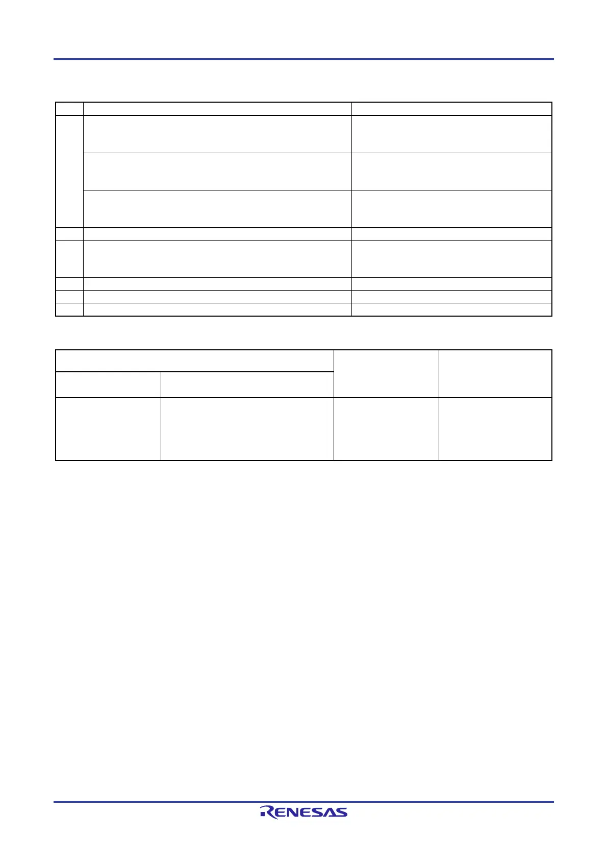
Table 17-4. Mode Transition Conditions
Step Mode transition Transition condition
(1) LIN reset mode → LIN mode
(LIN master mode)
LMD bits in LMDn register = 00b
and
OM1 and OM0 bits in LCUCn register = 01b or 11b
LIN reset mode → LIN mode
(LIN slave mode[auto baud rate])
LMD bits in LMDn register = 10b
and
OM1 and OM0 bits in LCUCn register = 01b or 11b
LIN reset mode → LIN mode
(LIN slave mode [fixed baud rate])
LMD bits in LMDn register = 11b
and
OM1 and OM0 bits in LCUCn register = 01b or 11b
(2) LIN mode → LIN reset mode OM0 bit in LCUCn register = 0b
(3) LIN reset mode → UART mode LMD bits in LMDn register = 01b
and
OM0 bit in LCUCn register = 1b
(4) UART mode → LIN reset mode OM0 bit in LCUCn register = 0b
(5) LIN reset mode → LIN self-test mode See 17.6 LIN Self-Test Mode.
(6) LIN self-test mode → LIN reset mode See 17.6 LIN Self-Test Mode.
Table 17-5.
Operations Available in Each Mode
LIN mode
UART mode LIN self-test mode
LIN master mode LIN slave mode [auto baud rate]/
LIN slave mode [fixed baud rate]
Header transmission
Response transmission
Response reception
Wake-up transmission
Wake-up reception
Error detection
Header reception
Response transmission
Response reception
Wake-up transmission
Wake-up reception
Error detection
UART transmission
UART reception
Error detection
Self test
Whether a transition has been caused to the LIN reset mode, the LIN mode, or the UART mode can be verified by reading
the LMD bits in the LMDn register or the OMM0 bit in the LMSTn register.
The maximum mode transition time (maximum time from when the value is set to the LSUCn register to when the value is
indicated in the LMSTn register) is the sum of three CPU clock (f
CLK) cycles and four cycles of the LIN communication clock
source (input clock to the LIN/UART module selected by LINnMCK).
For a description of the LIN self-test mode, see 17.6 LIN Self-Test Mode.

 Loading...


