RL78/F13, F14 CHAPTER 17 LIN/UART MODULE (RLIN3)
R01UH0368EJ0210 Rev.2.10 1202
Dec 10, 2015
(b) Response Transmission
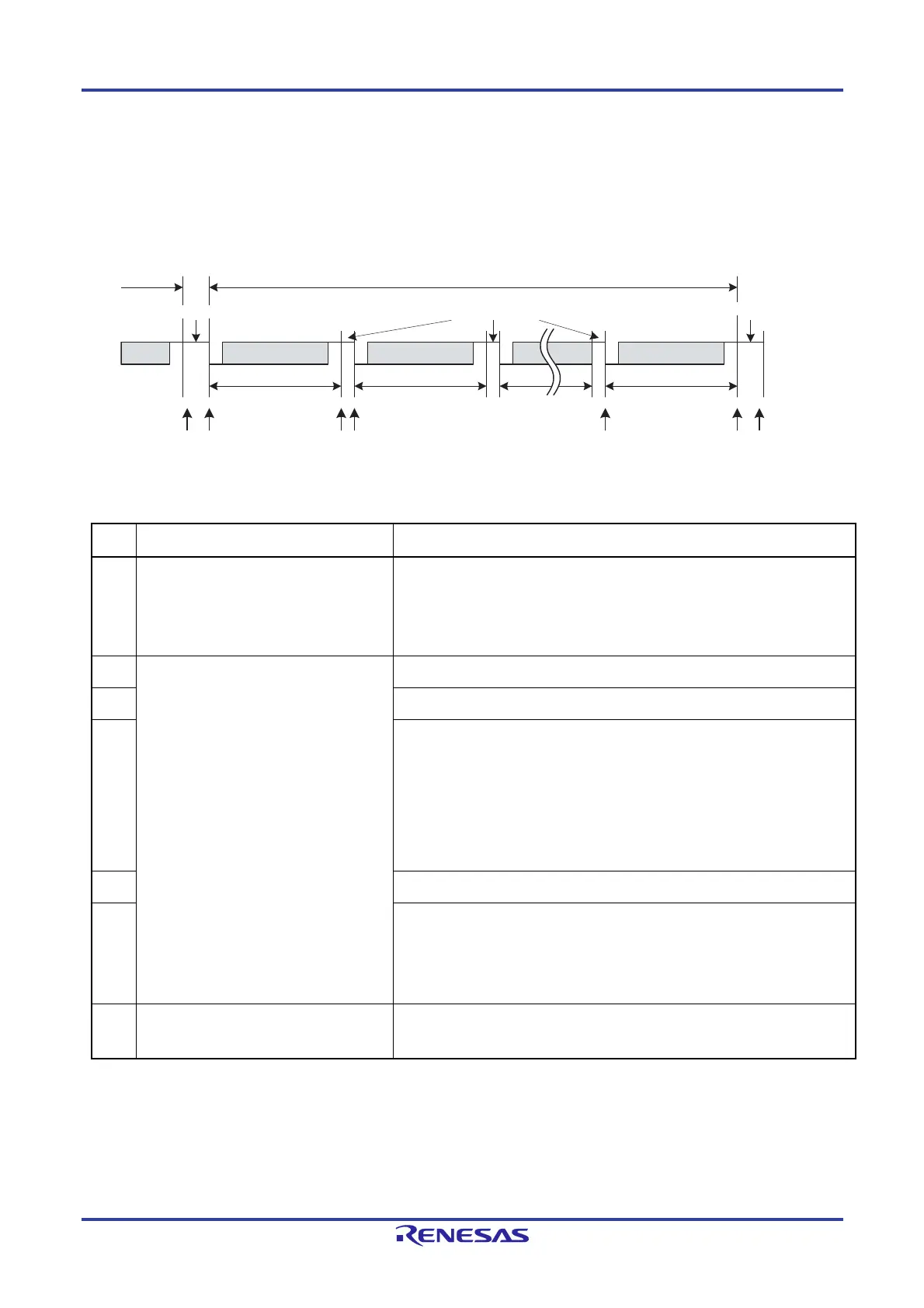
Figure 17-6 shows the operation of the LIN/UART module (LIN master mode) in response transmission. Table
17-8 provides processing in response transmission.
Figure 17-6. Operation in Response Transmission
Table 17-8.
Processing in Response Transmission
Step Software processing LIN/UART module processing
(1) (When in frame separate mode)
Sets the RTS bit in the LTRCn register to
1 (response transmission/reception
started).
(When not in frame separate mode)
Waits for an interrupt request .
(When in frame separate mode)
Waits for the setting of the RTS bit in the LTRCn register to 1 by software.
When the bit is set to 1, sends a response space.
(When not in frame separate mode)
Sends a response space.
(2) Waits for an interrupt request. Transmits the data 1.
(3) Transmits an inter-byte space.
(4)
Transmits the data 2.
Transmits an inter-byte space
Transmits the data 3.
Transmits an inter-byte space
(Repeats the transmission of inter-byte spaces as many times as the data
length specified in bits RFDL[3:0] in the LDFCn register, and stops the
transmission when the BER flag in the LESTn register is 1 (bit error detected).
If an error occurs, does not perform the Checksum transmission in item (5)).
:
(5) Transmits the checksum.
(6)
Sets a successful frame/wake-up transmission flag.
Sets the FTS bit in the LTRCn register to 0 (frame transmission or wake-up
transmission/reception stopped).
(When in frame separate mode)
Sets the RTS bit in the LTRCn register to 0 (response transmission/reception
stopped).
(7)
Processing after communication
Checks the LSTn register and clears
flags.
Idle
For information about error detection, refer to 17.4.6 Error Status.
Header
Inter-byte space
Response
(1) (2) (3)(4) (6) (7)(5)
Data 1
Data field Data field
Checksum
ChecksumData 2
Interrupt
ID +
parity
Response space
Inter-frame space

 Loading...


