RL78/F13, F14 CHAPTER 35 ELECTRICAL SPECIFICATIONS (GRADE K)
R01UH0368EJ0210 Rev.2.10 1732
Dec 10, 2015
(2/2)
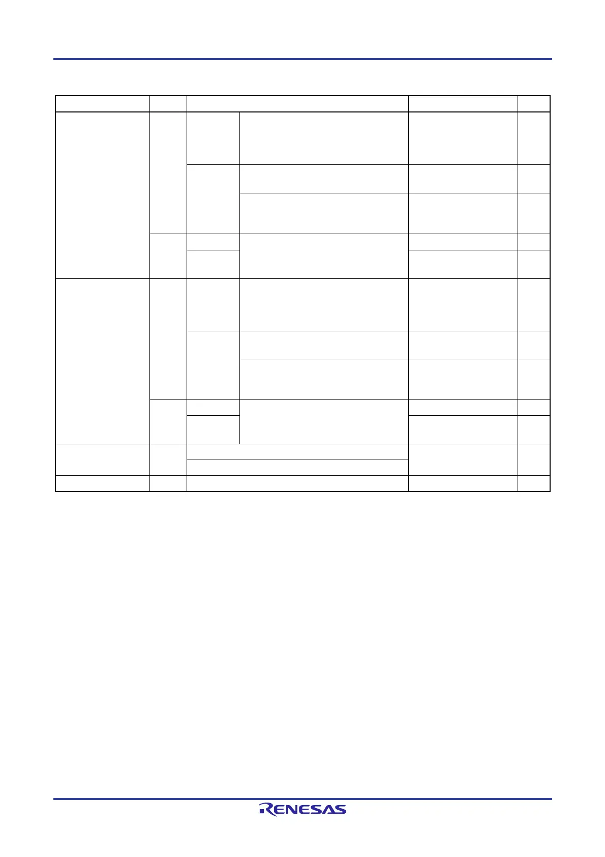
Parameter Symbol Conditions Ratings Unit
Output current, high IOH1 Per pin
P00 to P03, P10 to P17, P30 to P32, P40 to
P47, P50 to P57, P60 to P67, P70 to P77,
P92 to P97
Note
, P106, P107, P120, P125 to
P127, P130, P140, P150 to P157
-40 mA
Total of all
pins
-170 mA
P01, P02, P40 to P47, P92 to P97
Note
,
P120, P125 to P127, P150 to P153
-70 mA
P00, P03, P10 to P17, P30 to P32, P50 to
P57, P60 to P67, P70 to P77, P106, P107,
P130, P140, P154 to P157
-100 mA
IOH2 Per pin
P33, P34, P80 to P87, P90 to P97
Note
, P100
to P105
-0.5 mA
Total of all
pins
-2 mA
Output current, low IOL1 Per pin
P00 to P03, P10 to P17, P30 to P32, P40 to
P47, P50 to P57, P60 to P67, P70 to P77,
P92 to P97
Note
, P106, P107, P120, P125 to
P127, P130, P140, P150 to P157
40 mA
Total of all
pins
170 mA
P01, P02, P40 to P47, P92 to P97
Note
,
P120, P125 to P127, P150 to P153
70 mA
P00, P03, P10 to P17, P30 to P32, P50 to
P57, P60 to P67, P70 to P77, P106, P107,
P130, P140, P154 to P157
100 mA
IOL2 Per pin
P33, P34, P80 to P87, P90 to P97
Note
, P100
to P105
1 mA
Total of all
pins
5 mA
Operating ambient
temperature
T
A In normal operation mode -40 to +125 C
In flash memory programming mode
Storage temperature Tstg -65 to +150 C
Note For pin I/O buffer power supplies, refer to Table 4-1 Pin I/O Buffer Power Supplies.
Caution Product quality may suffer if the absolute maximum rating is exceeded even momentarily for any
parameter. That is, the absolute maximum ratings are rated values at which the product is on the
verge of suffering physical damage, and therefore the product must be used under conditions that
ensure that the absolute maximum ratings are not exceeded.
Remark Unless specified otherwise, the characteristics of alternate-function pins are the same as those of the port pins.

 Loading...


