RL78/F13, F14 CHAPTER 36 ELECTRICAL SPECIFICATIONS (GRADE Y)
R01UH0368EJ0210 Rev.2.10 1789
Dec 10, 2015
(T
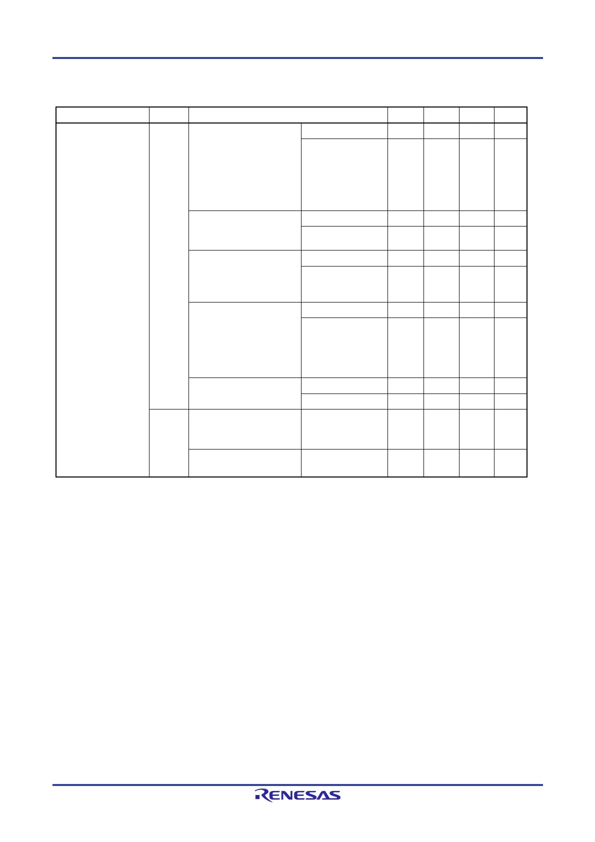
A = -40 to +150C, 2.7 V EVDD0 = EVDD1 = VDD 5.5 V, VSS = EVSS0 = EVSS1 = 0 V) (2/4)
Items Symbol Conditions MIN. TYP. MAX. Unit
Output current, low
Note 1
IOL1
Per pin for P00 to P03, P10
to P17, P30 to P32, P40 to
P47, P50 to P57, P60 to
P67, P70 to P77, P92 to
P97
Note 3
, P106, P107, P120,
P125 to P127, P130, P140,
P150 to 157
4.0 V EV
DD0 5.5 V
8.5 mA
2.7 V EVDD0 < 4.0 V
4.0 mA
Per pin for P10, P12, P14,
P30, P120, P140
(special slew rate)
4.0 V EV
DD0 5.5 V
0.59 mA
2.7 V EVDD0 < 4.0 V
0.07 mA
Total of P01, P02, P40 to
P47, P92 to P97
Note 3
, P120,
P125 to P127, P150 to P153
(for duty factors 70%
Note 2
)
4.0 V EV
DD0 5.5 V
20.0 mA
2.7 V EVDD0 < 4.0 V 15.0 mA
Total of P00, P03, P10 to
P17, P30 to P32, P50 to
P57, P60 to P67, P70 to
P77, P106, P107, P130,
P140, P154 to P157
(for duty factors 70%
Note 2
)
4.0 V EV
DD0 5.5 V
35.0 mA
2.7 V EVDD0 < 4.0 V 30.0 mA
Total of all pins
(for duty factors 70%
Note 2
)
4.0 V EV
DD0 5.5 V
55.0 mA
2.7 V EVDD0 < 4.0 V 45.0 mA
IOL2
Per pin for P33, P34, P80 to
P87, P90 to P97
Note 3
, P100
to P105
2.7 V V
DD 5.5 V 0.4 mA
Total of all pins
(for duty factors 70%
Note 2
)
2.7 V V
DD 5.5 V 5.0 mA
Notes 1. Value of current at which the device operation is guaranteed even if the current flows to the EVSS0, EVSS1 and
V
SS pins from an output pin.
2. These output current values are obtained under the condition that the duty factor is no greater than 70%.
The output current values when the duty factor is changed to a value greater than 70% can be calculated
from the following expression (when the duty factor is changed to n%).
Total output current of pins (I
OL 0.7)/(n 0.01)
<Example> Where n = 80% and IOL = 10.0 mA
Total output current of pins = (10.0 0.7)/(80 0.01) ≈ 8.7 mA
However, the current that is allowed to flow into one pin does not vary depending on the duty factor. A
current higher than the absolute maximum rating must not flow into one pin.
3. For pin I/O buffer power supplies, refer to Table 4-1 Pin I/O Buffer Power Supplies.
Remark Unless specified otherwise, the characteristics of alternate-function pins are the same as those of the port pins.
<R>

 Loading...


