RL78/F13, F14 CHAPTER 5 CLOCK GENERATOR
R01UH0368EJ0210 Rev.2.10 397
Dec 10, 2015
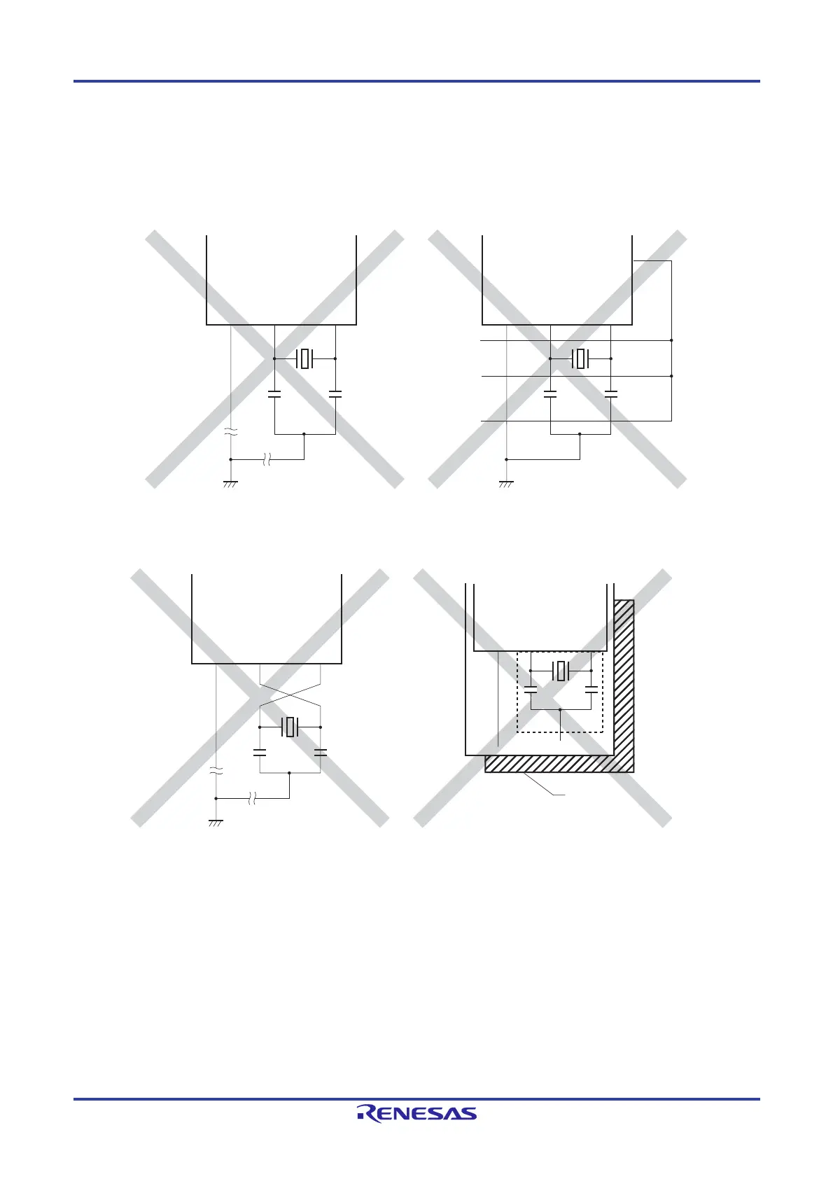
Figure 5-25 shows examples of incorrect resonator connection.
Figure 5-25. Examples of Incorrect Resonator Connection (1/2)
(a) Too long wiring (b) Crossed signal line
(c) The X1 and X2 signal line wires cross. (d) A power supply/GND pattern exists
under the X1 and X2 wires.
Note Do not place a power supply/GND pattern under the wiring section (section indicated by a broken line in the figure)
of the X1 and X2 pins and the resonators in a multi-layer board or double-sided board.
Do not configure a layout that will cause capacitance elements and affect the oscillation characteristics.
Remark When using the subsystem clock, replace X1 and X2 with XT1 and XT2, respectively. Also, insert resistors in
series on the XT2 side.
X2V
SS
X1 X1
NG
NG
NG
V
SS
X2
PORT
X2V
SS
X1
X1
Power supply/GND pattern
V
SS
X2
Note

 Loading...


