RL78/F13, F14 CHAPTER 6 TIMER ARRAY UNIT
R01UH0368EJ0210 Rev.2.10 489
Dec 10, 2015
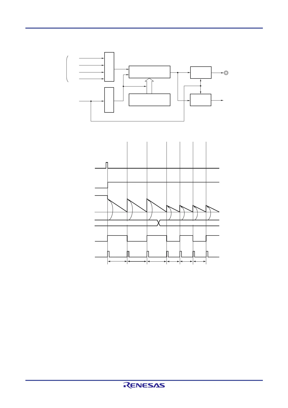
Figure 6-43. Block Diagram of Operation as Interval Timer/Square Wave Output
Figure 6-44. Example of Basic Timing of Operation as Interval Timer/Square Wave Output (MDmn0 = 1)
Remarks 1. m: Unit number (m = 0, 1), n: Channel number (n = 0 to 7)
2. TSmn: Bit n of timer channel start register m (TSm)
TEmn: Bit n of timer channel enable status register m (TEm)
TCRmn: Timer count register mn (TCRmn)
TDRmn: Timer data register mn (TDRmn)
TOmn: TOmn pin output signal
3. Unit 1 is not provided in the Group A products.
Channels 7 to 4 of unit 1 are not provided in the Group B, C, and D products.
CKm2
CKm3
TSmn
Timer counter
register mn (TCRmn)
TOmn pin
Interrupt signal
(INTTMmn)
Timer data
register mn(TDRmn)
Interrupt
controller
Output
controller
Clock selection
Trigger selection
Operation clock
CKm0
CKm1
TSmn
TEmn
TDRmn
TCRmn
TOmn
INTTMmn
a
a+1
b
0000H
a+1
a+1
b+1
b+1 b+1