RL78/F13, F14 CHAPTER 15 SERIAL ARRAY UNIT
R01UH0368EJ0210 Rev.2.10 919
Dec 10, 2015
(1) Register setting
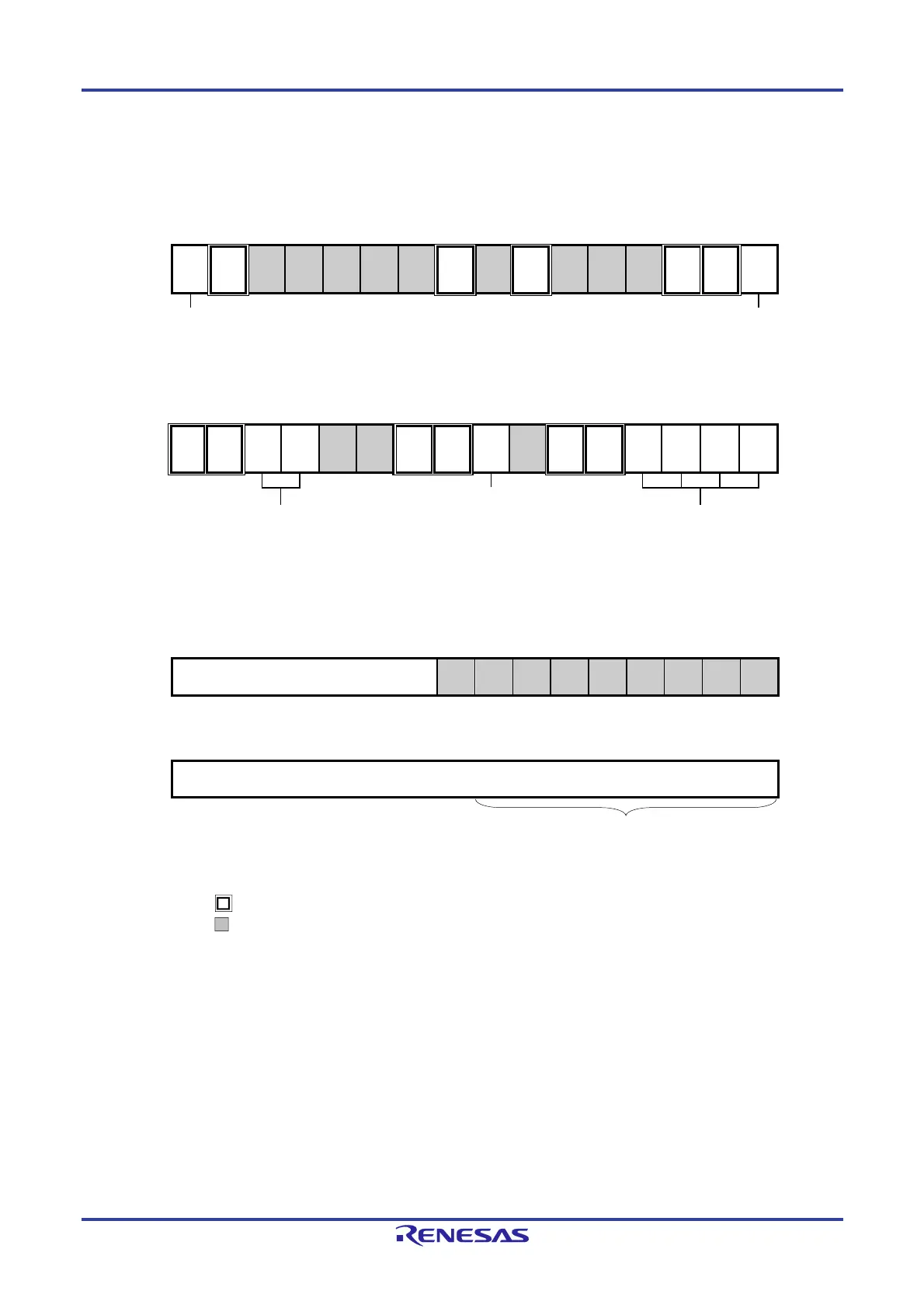
Figure 15-90. Example of Contents of Registers for Master Transmission/Reception of SPI Function
(CSI00, CSI01, CSI10, CSI11) (1/2)
(a) Serial mode register mn (SMRmn)
15 14 13 12 11 10 9 8 7 6 5 4 3 2 1 0
SMRmn
CKSmn
0/1
CCSmn
0
0
0
0
0
0
STSmn
0
0
SISmn0
0
1
0
0
MDmn2
0
MDmn1
0
MDmn0
0/1
Operation clock (fMCK) of channel n
0: Prescaler output clock CKm0 set by the SPSm register
1: Prescaler output clock CKm1 set by the SPSm register
Interrupt source of channel n
0: Transfer end interrupt
1: Buffer empty interrupt
(b) Serial communication operation setting register mn (SCRmn)
15 14 13 12 11 10 9 8 7 6 5 4 3 2 1 0
SCRmn
TXEmn
1
RXEmn
1
DAPmn
0/1
CKPmn
0/1
0
0
PTCmn1
0
PTCmn0
0
DIRmn
0/1
0
SLCmn1
0
SLCmn0
0
DLSmn3
0/1
DLSmn2
0/1
DLSmn1
0/1
DLSmn0
0/1
Selection of data transfer sequence
0: Inputs/outputs data with MSB first
1: Inputs/outputs data with LSB first.
Selection of the data and clock
phase (For details about the
setting, see 15.3 Registers
Controlling Serial Array Unit.)
Setting of data length
(c) Serial data register mn (SDRmn)
(1) When operation is stopped (SEmn = 0)
15 14 13 12 11 10 9 8 7 6 5 4 3 2 1 0
SDRmn
Baud rate setting
0
0
0
0
0
0
0
0
0
(2) When operation is in progress (SEmn = 1) (Lower 8 bits: SDRpL)
15 14 13 12 11 10 9 8 7 6 5 4 3 2 1 0
SDRmn
Transmit data setting/Receive data setting
Remarks 1. m: Unit number (m = 0, 1), n: Channel number (n = 0, 1), p: CSI number (p = 00, 01, 10, 11),
mn = 00, 01, 10, 11
2. : Setting is fixed in the CSI master transmission/reception mode
: Setting disabled (set to the initial value)
0/1: Set to 0 or 1 depending on the usage of the user
SDRpL

 Loading...


