10 August, 2001 SCANNER UNIT
6-5
Replacement
Adjustment
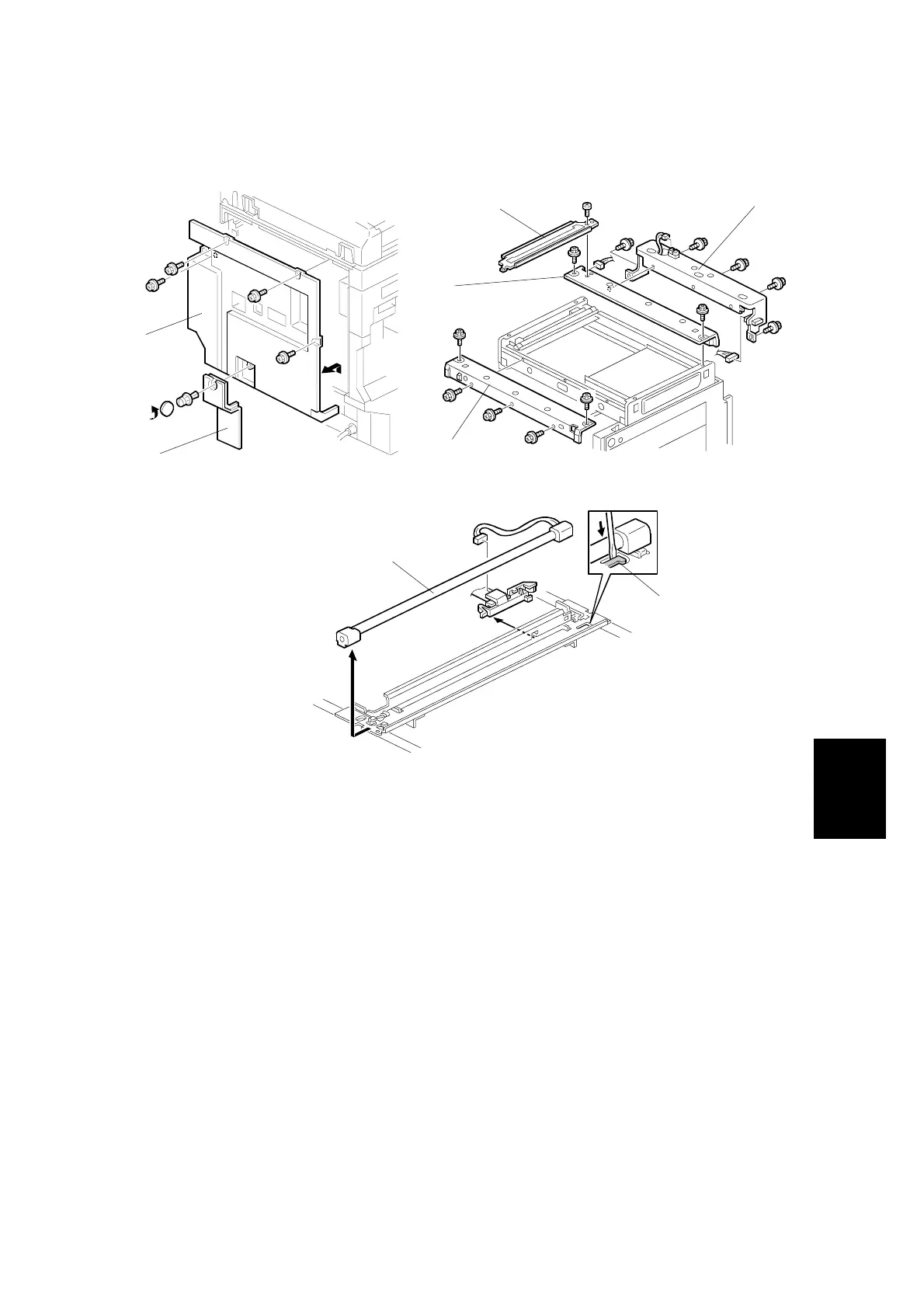
6.1.5 EXPOSURE LAMP
1. Remove the exposure glass. (☛ 6.1.1)
2. Remove the operation panel, rear cover, and left cover. (☛ 6.1.2)
3. Remove the connector cover [A], disconnect the cable, and remove the rear
cover [B] (4 screws).
4. Remove the left upper stay [C] (1 screw).
5. Remove the front frame [D] (5 screws).
6. Remove the rear bracket [E] (5 screws, 2 connectors).
7. Remove the rear frame [F] (2 screws, 1 connector).
8. Push down the part [G] then slide out the exposure lamp [H] (1 connector).
NOTE: 1) Do not touch the glass surface of the exposure lamp with bare hands.
2) After installing the lamp, the part [G] must be returned to the original
position.
B027R008.WMF
B027R515.WMF
B027R009.WMF
[C]
[D]
[E]
[F]
[H]
[G]
[A]
[B]
 Loading...