COPY ADJUSTMENTS: PRINTING/SCANNING 10 August, 2001
6-38
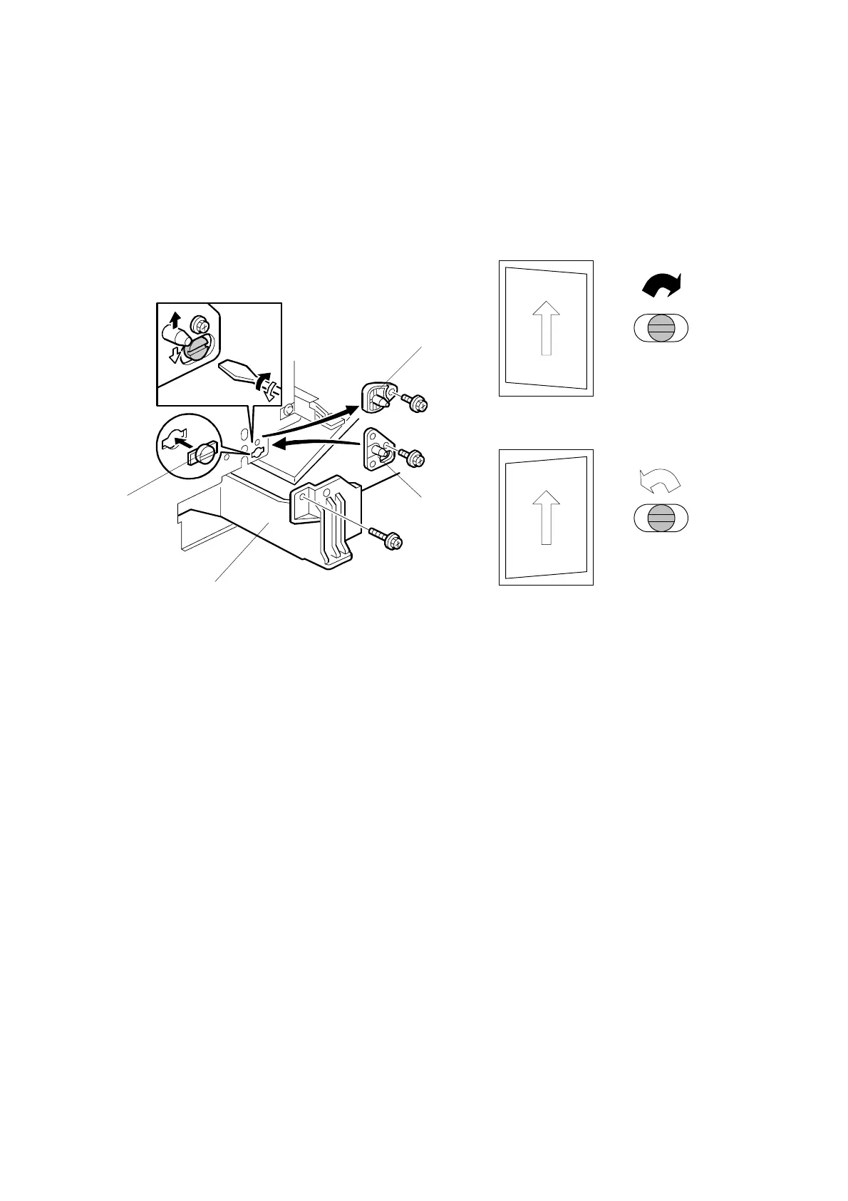
Parallelogram Image Adjustment
Do the following procedure if a parallelogram is printed while adjusting the printing
registration or the printing margin using a trimming area pattern.
NOTE: The following procedure should be done after adjusting the side-to-side
registration for each paper tray station.
1. Check whether the trimming area pattern (SP2-902, No.10) is printed as a
parallelogram, as shown. If it is, do the following.
2. Remove the laser unit [A] (☛ 6.2).
3. Remove the bracket [B] (2 screws).
4. Install the adjusting cam [C] (P/N: A2309003).
5. Secure the adjustment bracket [D] (P/N A2679002) using the screw which was
used for bracket [B]. However, do not tighten the screws at this time.
6. Adjusts the laser unit position by turning the adjusting cam. (Refer to the above
illustration for the relationship between the image and the cam rotation
direction).
7. Tighten the adjustment bracket.
8. Print the trimming area pattern to check the image. If it is still unsatisfactory,
repeat steps 4 to 8.
B027R013.WMF
Turn
clockwise
Turn
counterclockwise
B027R510.WMF
[A]
[B]
[C]
[D]
 Loading...