Home
Ricoh
All in One Printer
Russian-C2a
Ricoh Russian-C2a User Manual
4
of 1
of 1 rating
313 pages
Give review
Manual
Specs
To Next Page
To Next Page
To Previous Page
To Previous Page
Loading...
10 August, 2001
PAPER FEED
6-29
Replacement
Adjustment
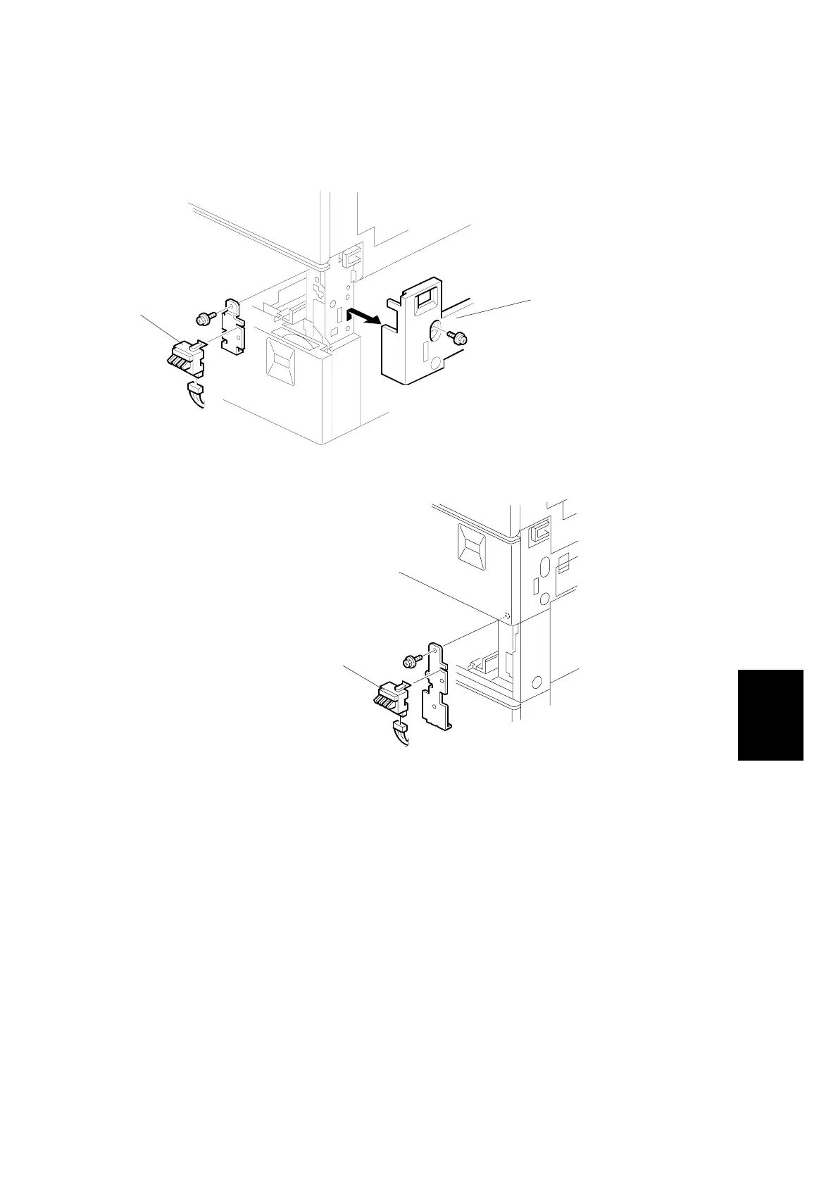
6.6.7
PAPER SIZE DETECTOR
1.
Remove the r
ight lower cov
e
r [A]. (
☛
6.
6.6)
2.
Remove th
e paper tray
s.
3.
Remove th
e paper
size detect
or assembly (1 scr
ew each).
4.
Replace the
paper size det
ectors [B] (1 c
onnector
each).
B027R721.W
MF
B022R722.W
MF
[A]
[B]
[B]
272
274
Table of Contents
Default Chapter
1
Service Manual
1
Laser Safety
3
Table of Contents
4
1 Overall Machine Information
18
Specifications
18
Machine Configuration
22
System Components
22
Installable Option Table
24
Copier Options
24
Fax Option
24
Printer/Scanner Options
24
Paper Path
25
Mechanical Component Layout
26
Electrical Component Descriptions
28
Electrical Component Layout
28
Electrical Component Description
29
Drive Layout
31
Copy Process
32
Overview
32
Board Structure
34
Overview
34
Controller
36
2 Detailed Section Descriptions
38
Scanning
38
Overview
38
Scanner Drive
39
Original Size Detection in Platen Mode
40
Image Processing
42
Overview
42
Sbu (Sensor Board Unit)
43
Auto Image Density
44
Ipu (Image Processing Unit)
45
Overview
45
Image Processing Modes
46
Image Processing Path
47
Overview
47
SP Modes for each Image Processing Step
48
Text Mode
48
Photo Mode
49
Text/Photo Mode
50
Pale Mode
51
Generation Copy
52
Auto Shading
53
Pre-Filtering
53
Main Scan Magnification/Reduction
53
Mirroring for ADF Mode
53
Characteristic Detection
54
Filtering
54
Overview
54
MTF Filter
54
Smoothing Filter
54
Characteristic Filter
54
Independent Dot Erase
55
Background Erase
55
Gradation Processing
55
Overview
55
Grayscale Processing
56
Binary Picture Processing
56
Error Diffusion
56
Dithering
56
Line Width Correction
56
Video Control Unit (Vcu)
57
Fine Character and Image (FCI)
57
Laser Exposure
58
Overview
58
Auto Power Control (Apc)
59
Ld Safety Switch
60
Photoconductor Unit (Pcu)
61
Overview
61
Drive
62
New Pcu Detection
63
Drum Charge
64
Overview
64
Charge Roller Voltage Correction
65
Correction for Environmental Conditions
65
ID Sensor Pattern Production Timing
66
Drum Charge Roller Cleaning
67
Development
68
Overview
68
Drive
69
Developer Mixing
70
Development Bias
71
Toner Supply
72
Toner Bottle Replenishment Mechanism
72
Toner Supply Mechanism
73
Toner Density Control
74
Overview
74
Toner Density Sensor Initial Setting
76
Toner Density Measurement
76
Vsp/Vsg Detection
76
Toner Supply Reference Voltage (Vref) Determination
76
Toner Supply Determination
76
Toner Supply Motor on Time Determinations
77
Toner Supply in Abnormal Sensor Conditions
78
ID Sensor
78
TD Sensor
78
Toner Near End/End Detection and Recovery
78
Toner Near End Detection
78
Toner Near End Recovery
79
Toner End Detection
79
Toner End Recovery
79
Drum Cleaning and Toner Recycling
80
Drum Cleaning
80
Toner Recycling
81
Paper Feed
82
Overview
82
Paper Feed Drive Mechanism
83
Paper Feed and Separation Mechanism
84
Paper Lift Mechanism
85
Paper End Detection
86
Paper Height Detection
87
Feed Pressure Adjustment for Paper Size
88
Overview
88
Paper Size Thresholds
88
Feed Pressure Adjustment
89
Effect of the Amount of Remaining Paper
89
From Tray Full to Paper Near-End
89
From Paper Near End to Paper End
90
Paper Size Detection
91
Special Paper Setting
92
Side and End Fences
93
Side Fences
93
End Fence
93
Paper Registration
94
Image Transfer and Paper Separation
95
Overview
95
Image Transfer Current Timing
96
Transfer Roller Cleaning
97
Paper Separation Mechanism
97
Image Fusing and Paper Exit
98
Overview
98
Fusing Drive and Release Mechanism
99
Fusing Entrance Guide Shift Mechanism
100
Pressure Roller
101
Cleaning Mechanism
101
Fusing Temperature Control
102
Temperature Control
102
Fusing Lamp Control
103
Overheat Protection
104
Paper Exit
104
Energy Saver Modes
105
Overview
105
Energy Saver Mode
106
Entering the Energy Saver Mode
106
What Happens in Energy Saver Mode
106
Return to Stand-By Mode
106
Auto off Mode
107
Entering off Stand-By and off Modes
107
Off Stand-By Mode
107
Off Mode
107
Returning to Stand-By Mode
107
3 Installation Procedure
108
Installation Requirements
108
Environment
108
Machine Level
108
Minimum Space Requirements
109
Power Requirements
110
Copier Installation
111
Power Sockets for Peripherals
111
Installation Flow Chart
112
Accessory Check
113
Installation Procedure
114
Paper Tray Unit Installation
118
Accessory Check
118
Installation Procedure
118
Lct Installation
121
Accessory Check
121
Installation Procedure
121
Auto Reverse Document Feeder Installation
124
Accessory Check
124
Installation Procedure
124
Interchange Unit Installation
127
Component Check
127
Installation Procedure
128
1-Bin Tray Unit Installation
130
Component Check
130
Installation Procedure
130
Shift Tray
133
Component Check
133
Installation Procedure
133
By-Pass Feed Unit Installation
135
Components Check
135
Installation Procedure
135
Duplex Unit Installation
137
Accessory Check
137
Installation Procedure
138
Bridge Unit Installation
140
Accessory Check
140
Installation Procedure
140
1,000-Sheet Finisher Installation
142
Accessory Check
142
Installation Procedure
143
500-Sheet Finisher Installation
146
Accessory Check
146
Installation Procedure
147
Platen Cover Installation
149
Memory (G578/G579)
150
Hdd (B420)
151
Key Counter Installation
153
Anti-Condensation Heater
155
Tray Heater
156
Tray Heater (Optional Paper Tray Unit)
158
Tray Heater (Optional Lct)
161
4 Service Tables
164
General Caution
164
Pcu (Photoconductor Unit)
164
Transfer Roller Unit
164
Scanner Unit
164
Laser Unit
165
Fusing Unit
165
Paper Feed
165
Others
165
Service Program Mode
166
Service Program Mode Operation
166
Entering and Exiting SP Mode
166
SP Mode Button Summary
167
Switching between SP Mode and Copy Mode for Test Printing
168
Selecting the Program Number
168
Service Program Mode Tables
169
SP1-XXX: Feed
169
SP2-XXX: Drum
179
SP4-XXX: Scanner
188
SP5-XXX: Mode
194
SP6-XXX: Peripherals
204
SP7-XXX: Data Log
206
Tray Shift
211
SP9-XXX: Debug/Testing
215
Test Pattern Printing (Sp2-902-3)
216
Input Check
217
Main Machine Input Check (SP5-803)
217
ARDF Input Check (SP6-007)
220
Original Trailing Edge Sensor
220
Finisher Input Check (SP6-117)
221
Output Check
223
Main Machine Output Check (SP5-804)
223
Paper Feed Clutch
223
ARDF Output Check (SP6-008)
225
Finisher Output Check (SP6-118)
225
Stamp
225
Smc Data Lists (Sp5-990)
226
Memory All Clear (Sp5-801)
227
Using a Flash Memory Card
227
Without Using a Flash Memory Card
228
Replacement and Adjustment
228
Uploading/Downloading Nvram Data
229
Uploading NVRAM Data (SP5-824)
229
Downloading NVRAM Data (SP5-825)
230
Aps Output Display (Sp4-301)
231
Df Aps Sensor Output Display (Sp6-901)
232
Nip Band Width Measurement (Sp1-109)
233
Program Download
234
Software Reset
235
System Settings and Copy Setting Reset
235
System Setting Reset
235
Copier Setting Reset
236
User Tools
237
System Settings
237
Copier/Document Server Features
238
Printer, Facsimile, Scanner Settings
238
Inquiry
238
Counter
239
Leds
240
Controller
240
Sbcu
240
Ipu
240
Dip Switches
240
Controller: DIP SW2
240
Sbcu: Dip Sw102
240
Special Tools and Lubricants
241
Special Tools
241
Lubricants
241
5 Preventive Maintenance Schedule
242
Pm Table
242
6 Replacement and Adjustment
245
Scanner Unit
245
Exposure Glass
245
Scanner Exterior/Operation Panel
246
Left Cover
246
Lens Block Assembly
247
Original Size Sensors
248
Exposure Lamp
249
Scanner Motor/Lamp Stabilizer
250
Scanner Wires
251
Laser Unit
254
Caution Decal Locations
254
Laser Unit
255
Polygon Mirror Motor
256
Ld Unit
256
Laser Synchronization Detector
257
Photoconductor Unit (Pcu)
258
Pcu
258
Transfer Unit
259
Transfer Roller Unit
259
Image Density Sensor
260
Thermistors
261
Fusing/Exit
261
Thermofuse
262
Hot Roller and Fusing Lamp
264
Pressure Roller/Cleaning Roller
265
Paper Exit Sensor/Paper Overflow Sensor
266
Paper Feed
267
Feed Rollers
267
Paper End Sensor
268
Paper Tray Lift Motors
269
Registration Clutch
270
Paper Feed Clutches
271
Lower Paper Feed Clutch
271
Upper Paper Feed Clutch
271
Relay Clutches
272
Paper Size Detector
273
Registration Sensor
274
Relay Sensors
275
Upper Relay Sensor
275
Lower Relay Sensor
275
Pcbs and Other Items
276
Controller Board
276
Sbcu Board
277
Main Motor
278
Psu
279
Copy Adjustments: Printing/Scanning
280
Printing
280
Registration - Leading Edge/Side-To-Side
280
Blank Margin
281
Main Scan Magnification
281
Parallelogram Image Adjustment
282
Scanning
283
Registration: Platen Mode
283
Magnification
283
Standard White Density Adjustment
284
Adf Image Adjustment
285
Registration
285
Sub Scan Magnification
285
Touch Screen Calibration
286
7 Troubleshooting
287
Service Call Conditions
287
Sc Code Descriptions
288
Rear Fence Motor
290
Self-Diagnostic Mode
298
Self-Diagnostic Mode at Power on
298
Detailed Self-Diagnostic Mode
299
Feed Belt
302
Electrical Component Defects
303
Switches
305
Blown Fuse Conditions
306
Registration Sensor
312
Paper Size
313
4
Based on 1 rating
Ask a question
Give review
Questions and Answers:
Need help?
Do you have a question about the Ricoh Russian-C2a and is the answer not in the manual?
Ask a question
Ricoh Russian-C2a Specifications
General
Brand
Ricoh
Model
Russian-C2a
Category
All in One Printer
Language
English
Related product manuals
Ricoh RN-MF1
162 pages
Ricoh MP C3004
2154 pages
Ricoh Pro 8300S
188 pages
Ricoh Aficio 1515
68 pages
Ricoh Pro C7100sx
276 pages
Ricoh Aficio MP 4001
81 pages
Ricoh Aficio MP C2000
236 pages
Ricoh Aficio MP C2050
328 pages
Ricoh Aficio MP C3500
236 pages
Ricoh Aficio MP C2030
136 pages
Ricoh Aficio SP 100SU e
76 pages
Ricoh Aficio MP C2500 Series
6 pages
 Loading...