COPY ADJUSTMENTS: PRINTING/SCANNING 10 August, 2001
6-36
6.8 COPY ADJUSTMENTS: PRINTING/SCANNING
NOTE: 1) You need to perform these adjustment(s) after replacing any of the
following parts:
• Scanner Wire
• Lens Block/SBU Assembly
• Scanner Drive Motor
• Polygon Mirror Motor
• Paper Side Fence
• Memory All Clear
2) For more details about accessing SP modes, refer to section 4.
6.8.1 PRINTING
NOTE: 1) Make sure the paper is installed correctly in each paper tray before you
start these adjustments.
2) Use the Trimming Area Pattern (SP2-902-3, No.10) to print the test
pattern for the following procedures.
3) Set SP 2-902-3 to 0 again after completing these printing adjustments.
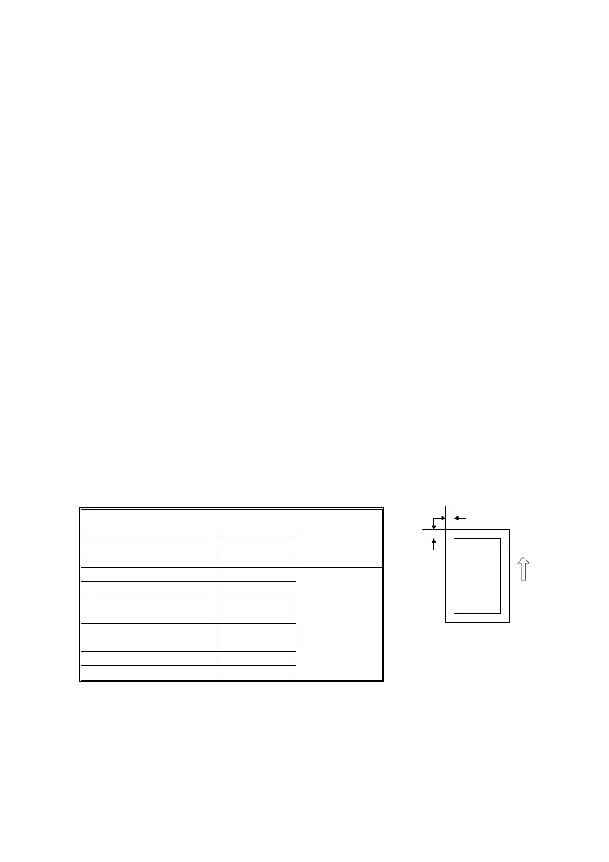
Registration - Leading Edge/Side-to-Side
1. Check the leading edge registration for each paper feed station, and adjust
them using SP1-001.
2. Check the side-to-side registration for each paper feed station, and adjust them
using SP1-002.
Tray SP mode Specification
Any paper tray SP1-001-1
By-pass feed SP1-001-2
Duplex SP1-001-3
3 ± 2 mm
1st paper feed SP1-002-1
2nd paper feed SP1-002-2
3rd paper feed (Optional
PFU tray 1), or LCT
SP1-002-3
2 ± 1.5 mm
4th paper feed (Optional
PFU tray 2)
SP1-002-4
By-pass feed SP1-002-5
Duplex, side 2 SP1-002-6
A: Leading Edge Registration
B: Side-to-side Registration
_
^
B027R508.WMF
 Loading...