Parameterizing machine data
3.2 Parameterizing the control using machine data
HMI Advanced (IM4)
108 Commissioning Manual, 03/2009, 6FC5397-0DP10-3BA0
3.2.11 Representing the spindle utilization
Function
Up to now, the display range of the spindle utilization in the Machine main screen was
represented at 100%. You can set the display range of the bar graph for representation of
the spindle load to 200% using display MD 9429: MA_SPIND_POWER_RANGE.
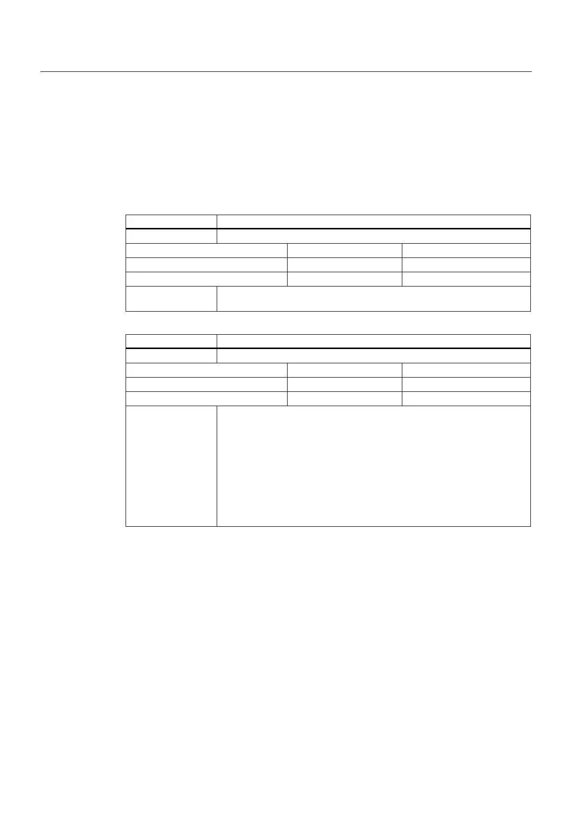
9428 $MM_MA_SPIND_MAX_POWER
MD number Maximum value of the spindle power display
Default setting: 100 Min. input limit: 100 Max. input value: ****
Changes effective after: POWER ON Protection level: 3/4 Units: %
Data type: WORD Applies from SW version: 6.4
Significance In this MD, enter the factor by which the supplied spindle utilization will be
multiplied.
9429 $MM_MA_SPIND_POWER_RANGE
MD number Display range for spindle utilization
Default setting: 100 Min. input limit: 100 Max. input value: ****
Changes effective after: POWER ON Protection level: 3/4 Units: %
Data type: WORD Applies from SW version: 6.4
Significance In this MD, you specify the display range of the bar graph for the spindle
utilization display. Depending on the value entered, the percentage values
displayed and the extent of the color areas change.
Value 100:Percentage values 0%, 80%, and 100% are displayed. The color
display changes from green to red starting at 80% if a value of 100 is also set
in display MD 9428.
Value > 100, e.g. 200:Percentage values 0%, 200%, and 100% are displayed.
The color display changes from green to red starting at 100%.
If you set the value to 200, you must enter the normalization factor in display
MD $MM_MA_SPIND_MAX_POWER.
 Loading...