3RT1/3RH1 contactors
SIRIUS System Manual
GWA 4NEB 430 0999-02b
3-5
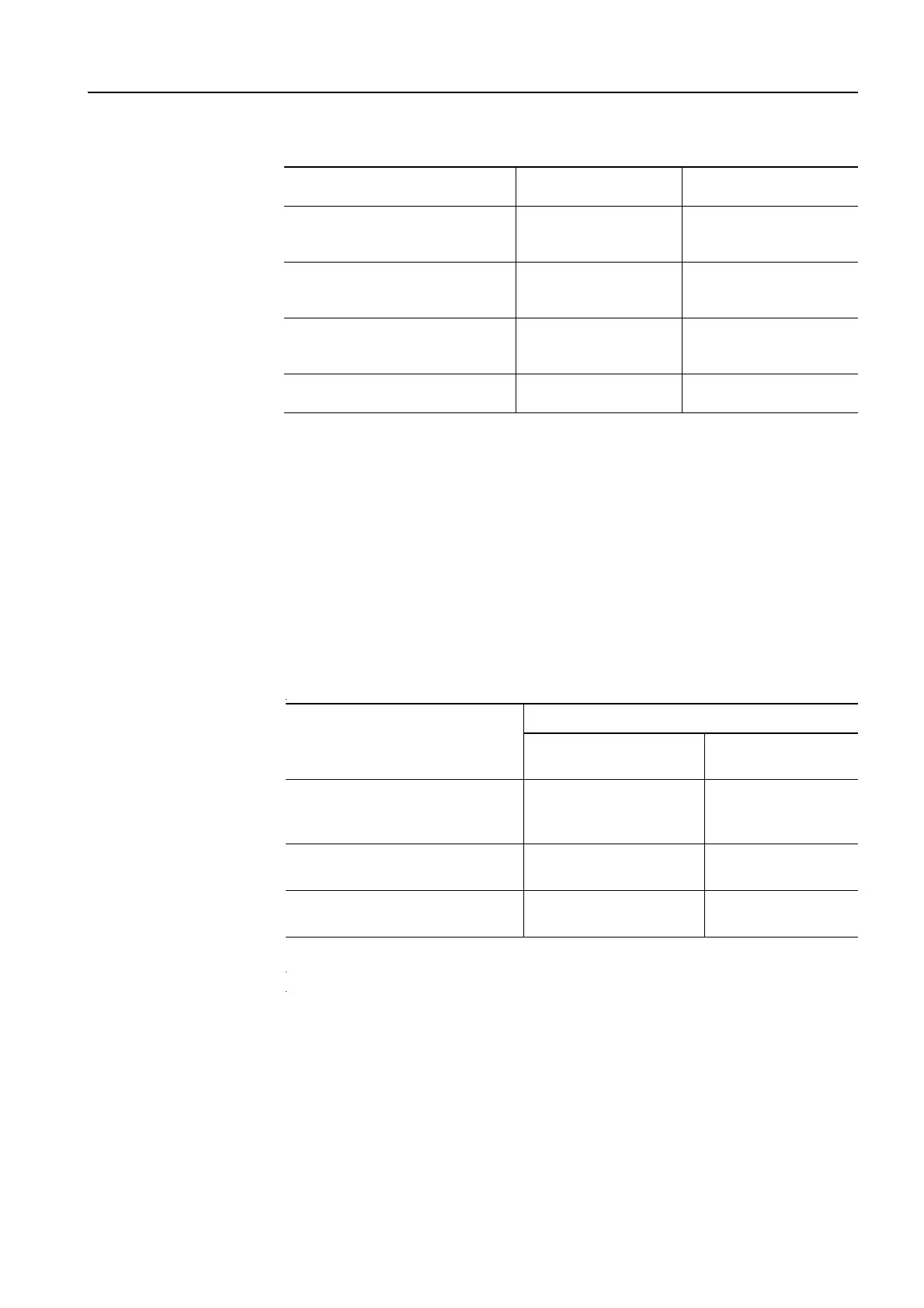
Utilization category for
DC voltages
Table 3-2: Utilization categories, test conditions for DC voltages
Definition of DC-1 to
DC-6
The definitions of the utilization categories DC-1 to DC-6 apply to main cir-
cuits for switching DC voltage.
The main areas of application for contactors are:
• DC-3/DC-5 operation: switching of shunt or series motors
• DC-1 operation: switching of resistive loads, resistance furnaces
Note:
In the information on DC switching capacity in previous documents, the uti-
lization categories DC-2 and DC-4 correspond to the current utilization cate-
gories DC-3 and DC-5.
Utilization category for
AC voltage (auxiliary
contact elements)
Table 3-3: Utilization categories, test conditions for AC voltage (auxiliary contact elements)
Definition of AC-12 to
AC-15
IEC 60 947-5-1/EN 60 947-5-1 (VDE 0660 Part 200) contains the definitions
of the utilization categories AC-12 to AC-15 for switching elements for the
control, signaling, locking, etc. of switchgear and controlgear.
The main areas of application for auxiliary contactors are:
• AC-14/AC-15 operation: switching of contactor coils, solenoid valves, for
example
• AC-14/AC-12 operation: switching of resistive loads, for example
DC Utilization category for
DC voltages
Switching capacity I/I
e
Make/break
Switching capacity
Time constant
L
/
R
(ms)
DC-1 Not an inductive load or
a slightly inductive load,
resistance furnaces
1. 5 1. 0
DC-3 Shunt motors:
switching on, plugging,
reversing, inching
4.0 2.5
DC-5 Series motors:
switching on, plugging,
reversing, inching
4.0 15
DC-6 Switching of incandescent
lamps
1.5 (Incandescent lamp
test)
AC Utilization category for
AC voltage (auxiliary
contact elements)
Switching capacity
Make
I/I
e
Break
I/I
e
cos
ϕ
AC-12 Control of resistive load and
semiconductor load in the input cir-
cuits of optocouplers
110.9
AC-14 Control of a small electro-
magnetic load (max. 72 VA)
610.3
AC-15 Control of an electromag-
netic load (greater than 72 VA)
10 1 0.3