3RT1/3RH1 contactors
SIRIUS System Manual
3-68
GWA 4NEB 430 0999-02b
Notes on configuration
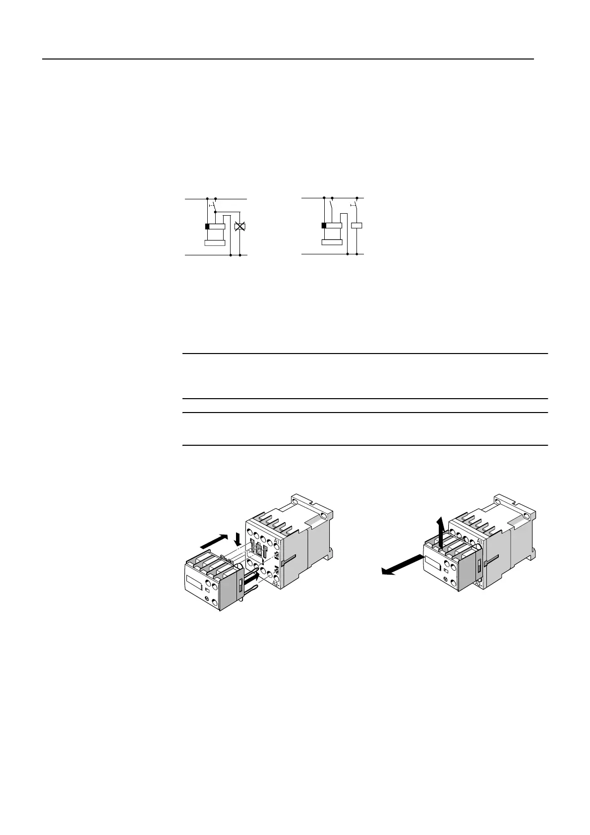
The control of loads parallel to the start input is not permissible in AC opera-
tion. See the relevant circuit diagram
¿
below.
The off-delay solid-state time relay blocks (3RT1916-2D.../3RT1926-2D...)
have a live start input (B1). With AC voltage, this can imitate the control of a
parallel load on the B1 terminal. In this case, an additional load (contactor
K3, for example) should be wired as shown in circuit diagram
À
.
Figure 3-46: Control of loads
3.4.3.1 Frame size S00 (3RT1916-2C, -2D)
Caution
Switch off the supply voltage to A1/A2 before you install or remove the
solid-state time relay block.
Installation/removal
Important
The time-delay auxiliary switch cannot be attached to contactor relays.
The solid-state time relay block of frame size S00 is attached to the front of
the contactor and latched into place with a pushing movement.
Figure 3-47: Solid-state time relay block with semiconductor output, installation (frame size S00)
Connection
When the solid-state time relay block is installed, it is connected at the
same time with the A1 and A2 coil connections of the contactor by the plug-
in contacts. Coil connections of the contactor that are not required are cov-
ered by covers on the housing of the time relay block, thus preventing inad-
vertent connection.
N
L1
S1
A2A1 B1
A2A1
K3
K1
K2
N
L1
K3
A2A1 B1
A2A1
S1
K3
K1
K2
K1 time relay block
K2 contactor