3RT1/3RH1 contactors
SIRIUS System Manual
3-24
GWA 4NEB 430 0999-02b
Assembly of the con-
tactors in frame size S0
with lateral interlocking
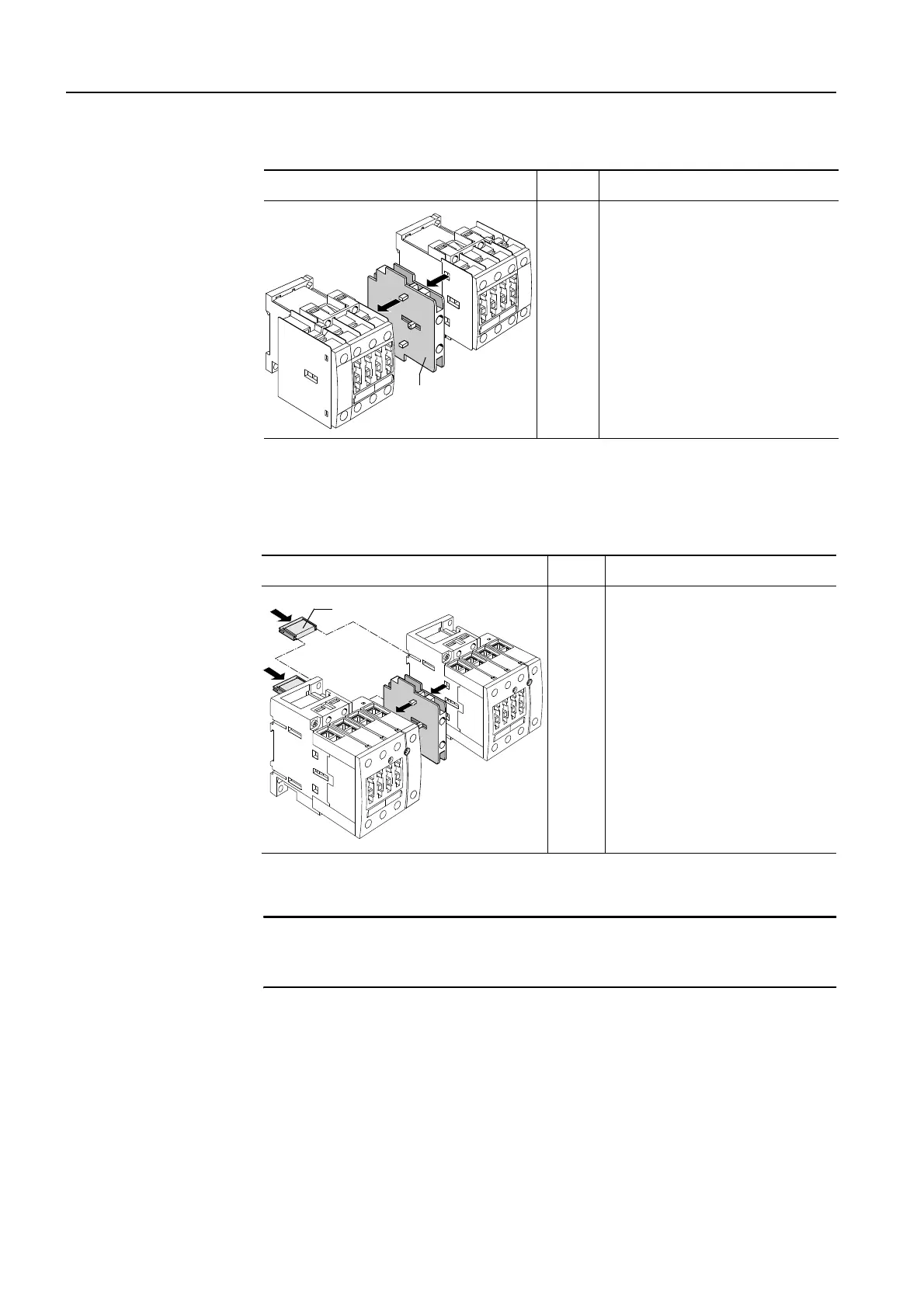
Table 3-14: 4-pole reversing contactor combination with lateral interlock (frame size S0)
Assembly of the con-
tactors in
frame sizes S2/S3
Table 3-15: 4-pole reversing contactor combination (frame sizes S2 and S3)
Attention
The mechanical interlock at the front cannot be used in contactors in frame
sizes S2 and S3.
Drawing: frame size S0 Step Procedure
5/6 Note:
The lateral mechanical inter-
lock (3RA1924-2B) can be used
if the contactor combination is
to be mounted on a base plate.
6
5
3RA1924-2B
Drawing: frame sizes S2 and S3 Step Procedure
1/2
Mount the mechanical inter-
lock between the two contac-
tors
(1/2),
and insert the 2
connecting clips (10 mm spa-
cing)
(3)
on the back of the
two contactors.
2
3
3
1
3RA19.2-2G