3RW3 semiconductor motor control unit
SIRIUS System Manual
GWA 4NEB 430 0999-02b
8-19
Table 8-5: Stand-alone installation, minimum clearances at the side, 3RW3
Table 8-6: Stand-alone installation, minimum clearances at the side, 3RW3
Line lengths for the
drive circuit
The control inputs for starting and stopping are not rated for longer dis-
tances. This means:
• In the case of a drive circuit that goes beyond the control cubicle, cou-
pling relays must be used.
• The control cables in the cubicle should not be laid together with main cir-
cuit cables.
When electronic output modules are used in the drive circuit (e.g. Triac out-
puts at 230 VAC), RC elements (e.g. 3TX7462-3T or similar with C > 100 nF)
may be required at the control inputs under certain circumstances.
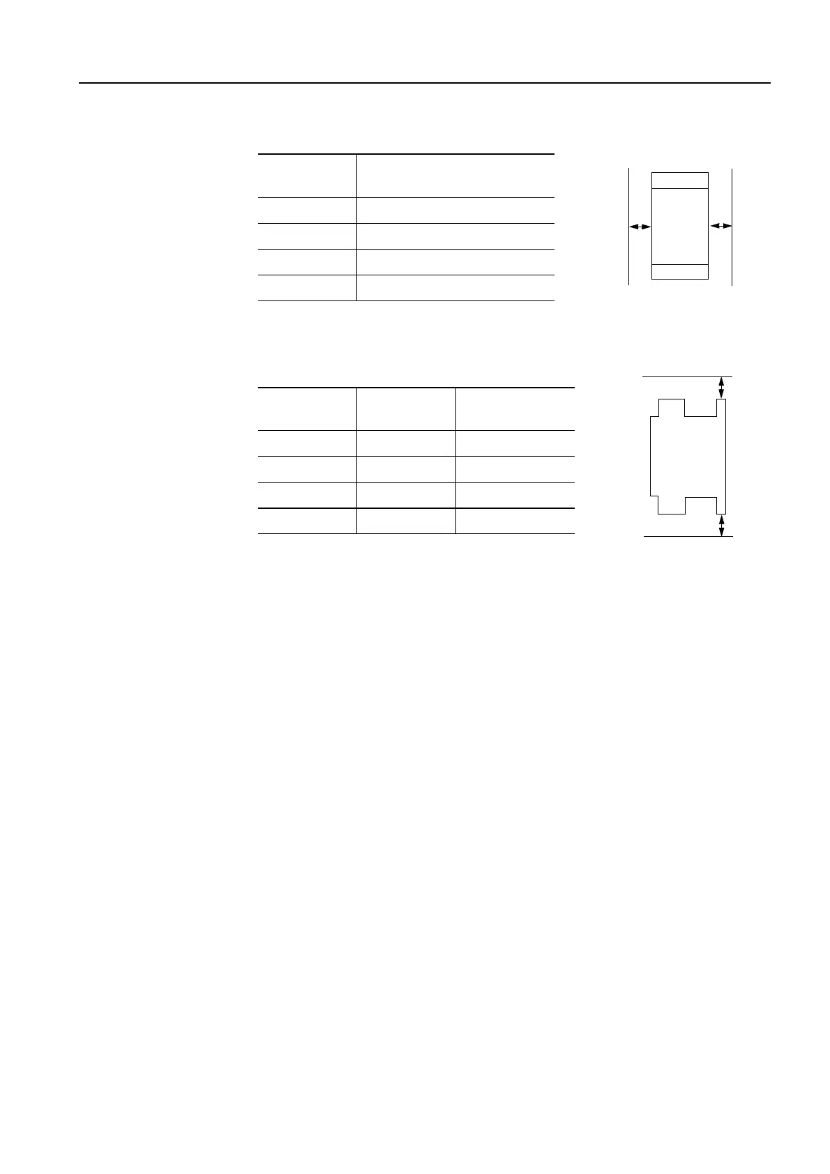
Frame size
Minimum clearance on
both sides in mm
S00 15
S0 20
S2 30
S3 40
3RW30
a
b
3RW30
Frame size
Vertical
clearance a
Vertical
clearance b
S00 50 50
S0 60 40
S2 50 30
S3 60 30