3RT1/3RH1 contactors
SIRIUS System Manual
3-54
GWA 4NEB 430 0999-02b
The following table shows you the expansion options for the different frame
sizes:
Table 3-23: Expansion options for auxiliary switch blocks
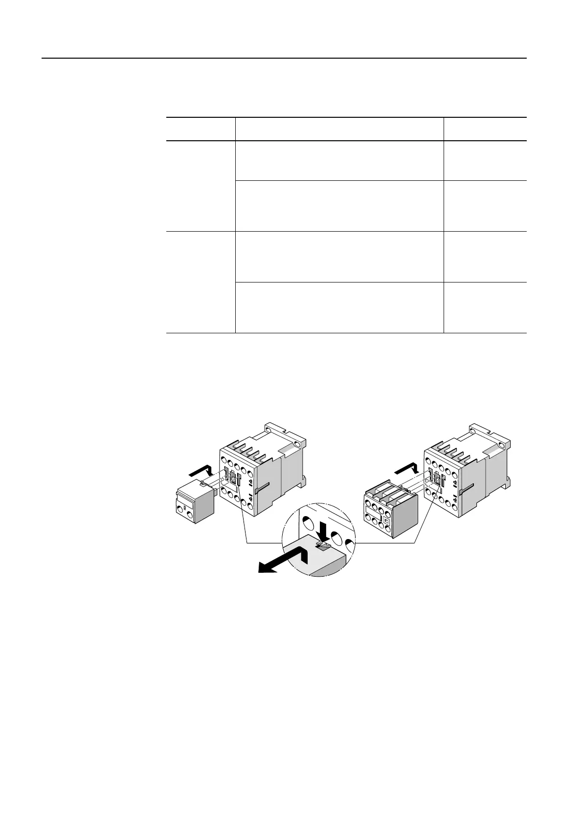
Auxiliary switch at front
Auxiliary switches that can be attached at the front are hooked into the
opening of the contactors and pulled down until they snap into place. They
can be removed using the release lever in the middle.
Figure 3-31: Auxiliary switch at front
Frame size Auxiliary switch block Connection
S00 1, 3 and 4-pole (attachable at the front) Screw-type/Cage
Clamp terminal
Feeder auxiliary switch (attachable at the front):
• 1-pole (1 NO or 1 NC contact)
• 2-pole (1 NO + 1 NC or 2 NO contacts)
Infeed from above or below possible
Screw-type termi-
nal
S0 to S3 1, and 4-pole (attachable at the front)
2-pole (attachable at the side)
Screw-type/Cage
Screw-type termi-
nal
Clamp terminal
Feeder auxiliary switch (attachable at the front):
• 2-pole (1 NO + I NC contact)
• 2-pole (2 NO or 2 NC contacts)
Infeed from above or below possible
Screw-type termi-
nal
2
1
 Loading...


