System overview
SIRIUS System Manual
1-20
GWA 4NEB 430 0999-02b
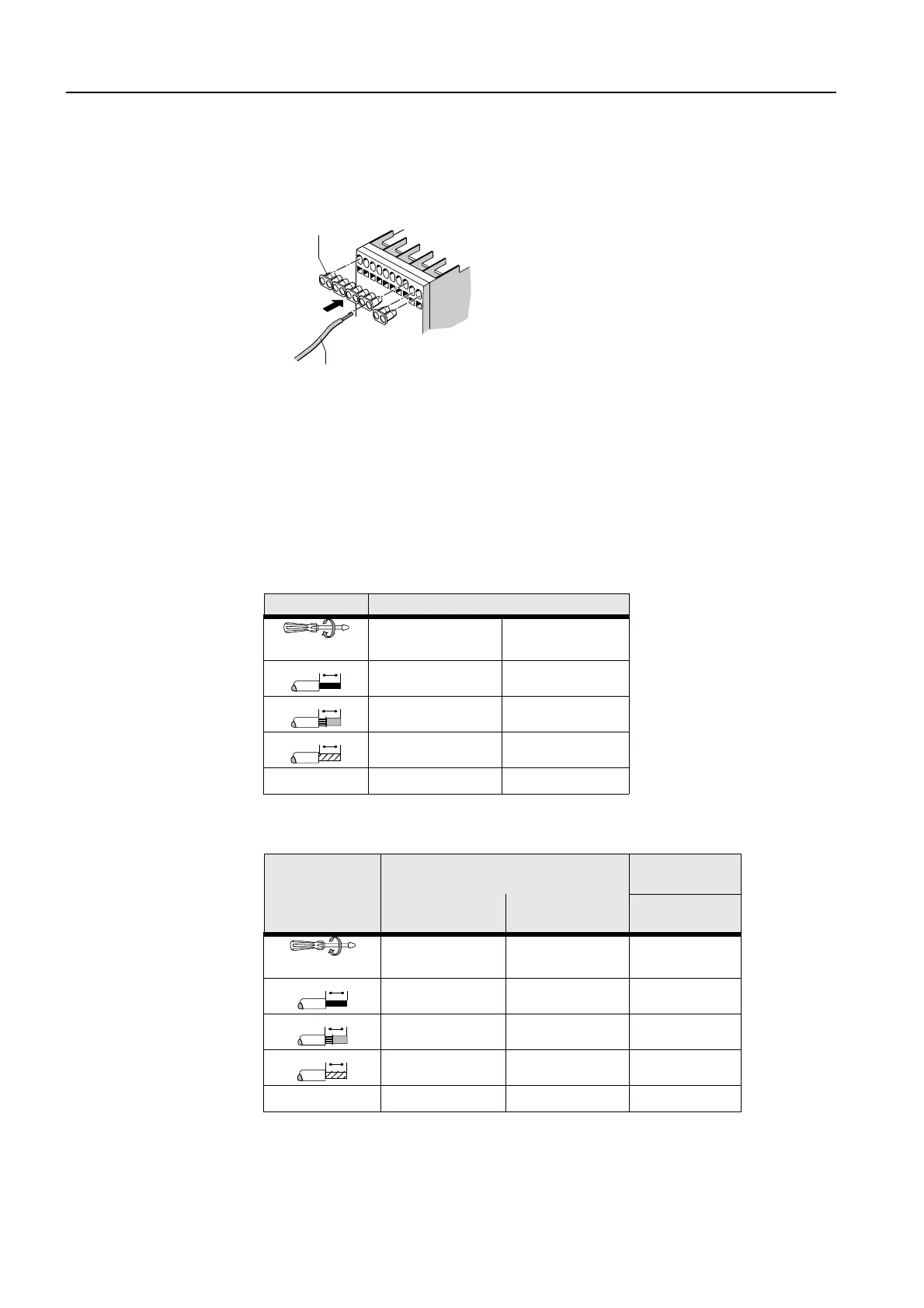
Small conductor cross-
sections
With conductor cross-sections that are
≤
1 mm
2
, you have to use an insula-
ting stop to ensure the conductors remain securely clamped.
The illustration below shows the procedure:
Figure 1-9: Conductor cross-sections ≤ 1 mm²
1.5.4 Connection cross-sections
Because SIRIUS is a modular system, the connection cross-sections are the
same for all devices of a single frame size.
The following tables specify the permissible conductor cross-sections for
main and auxiliary conductor connections:
Frame size S00
Table 1-6: Connection cross-section for frame size S00
Frame size S0
Table 1-7: Connection cross-section for frame size S0
≤ 1 mm²
3RT1916-4JA02
Main and auxiliary conductors
∅
5 to 6 mm/PZ2
0.8 to 1.2 Nm
7 to 10.3 lb.in
Cage Clamp
2 x (0.5 to 1.5 mm²)
2 x (0.75 to 2.5 mm²)
2 x (0.25 to 2.5 mm²)
2 x (0.5 to 1.5 mm²)
2 x (0.75 to 2.5 mm²)
2 x (0.25 to 1.5 mm²)
---- 2 x (0.25 to 2.5 mm²)
AWG
2 x (18 to 14) 2 x (24 to 14)
10
10
10
Control conductor: A1/A2
Auxiliary conductor: NO/NC
Main conductor
Screw-type
terminal
Cage Clamp
terminal
L1 L2 L3
T1 T2 T3
∅
5 to 6 mm/PZ2
0.8 1.2 Nm
7 to 10.3 lb.in
----
2 to 2.5 Nm
18 to 22 lb.in
2 x (0.5 to 1.5 mm²)
2 x (0.75 to 2.5 mm²)
2 x (0.25 to 2.5 mm²)
2 x (1 to 2.5 mm²)
2 x (2.5 to 6 mm²)
2 x (0.5 to 1.5 mm²)
2 x (0.75 to 2.5 mm²)
2 x (0.25 to 1.5 mm²)
2 x (1 to 2.5 mm²)
2 x (2.5 to 6 mm²)
---- 2 x (0.25 to 2.5 mm²) ----
AWG
2 x (18 to 14) 2 x (24 to 14) 2 x (14 to 10)
10
10
10