3RT1/3RH1 contactors
SIRIUS System Manual
3-78
GWA 4NEB 430 0999-02b
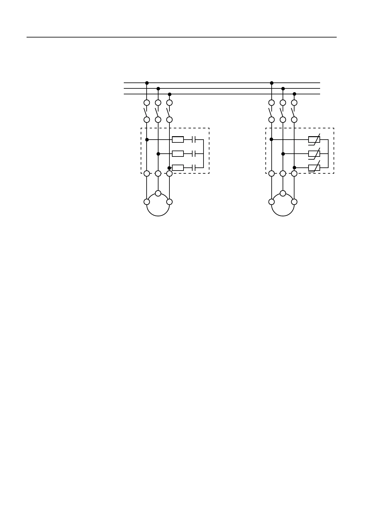
Circuit diagrams
Figure 3-60: RC element/varistor, circuit diagrams
3.4.7 Other accessories
3.4.7.1 LED module for indicating contactor control (3RT1926-1QT00)
Description
The LED module can be connected to the coil terminals of the contactors of
frame sizes S0 to S3. It indicates the status of the contactors by means of
yellow LEDs.
Mode of operation
The LED module can be used for AC/DC voltages of 24 V to 240 V.
The LEDs are connected bidirectionally to protect against polarity reversal.
Both LEDs light up in AC control, and one lights up in DC control, depending
on the polarity.
Connection
The LED module is connected to the A1 and A2 coil terminals of the contac-
tor.
L1
L3
L2
R_L1
R_L2
R_L3
C_L1
C_L2
C_L3
U
U
U
M
3~
M
3~
2T1 4T2 6T3 2T1 4T2 6T3
RC element
3RT1916-1PA.
Varistor
3RT1916-1PB.
V_L1
V_L2
V_L3