3RH, 3TX, LZX coupling links
SIRIUS System Manual
GWA 4NEB 430 0999-02b
6-15
Conductor cross-sec-
tions
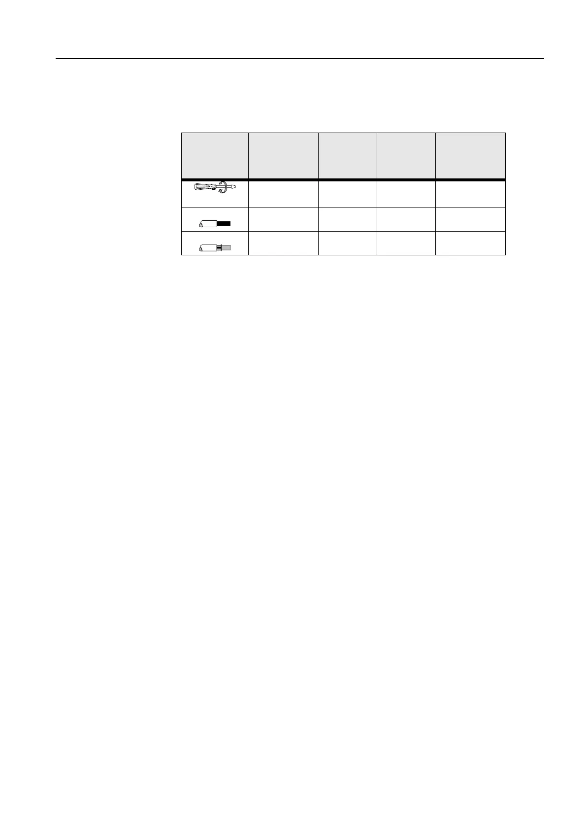
The following table shows the permissible conductor cross-sections for the
coupling links. The specifications apply to main and auxiliary connections.
Table 6-5: Conductor cross-sections for the 3RH, 3TX, and LZX coupling links
3TX7004
3TX7002
screw-type termi-
nals
3TX7005
3TX7003
Cage Clamp
terminals
LZX:
RT/ZT/MT
3RH1924
3TX7090
Screw-type termi-
nals
∅
5 to 6 mm / PZ2
M3 ------ ------ M3
1 x 0.25 to 4 mm² 1 x 0.08 to 2.5 mm² 2 x 2.5 mm² 2 x (0.5 to 2.5) mm²
1 x 0.5 to 2.5 mm² 1 x 0.25 to 2.5 mm² 2 x 1.5 mm² 2 x (0.5 to 1.5) mm²