3RP10, 3RP15 solid-state time relays
SIRIUS System Manual
GWA 4NEB 430 0999-02b
7-23
Screw-on attachment
Screw-on attachment is possible by means of push-in lugs for M4 screws
(application, see under Section 7.4 Accessories)
7.5.2 Connection
The 3RP10 solid-state time relays are available with SIGUT
terminals with
plus/minus Pozidriv 2 screws and also with Cage Clamp terminals.
The 3RP15 solid-state time relays are available:
•With SIGUT
terminals with plus/minus Pozidriv 2 screws
• With Cage Clamp terminals
Conductor cross-sec-
tions
The following table lists the permissible conductor cross-sections for the
3RP1 solid-state time relays. The specifications apply to control and load
current connections.
Table 7-7: Permissible conductor cross-sections for control and load current connections:
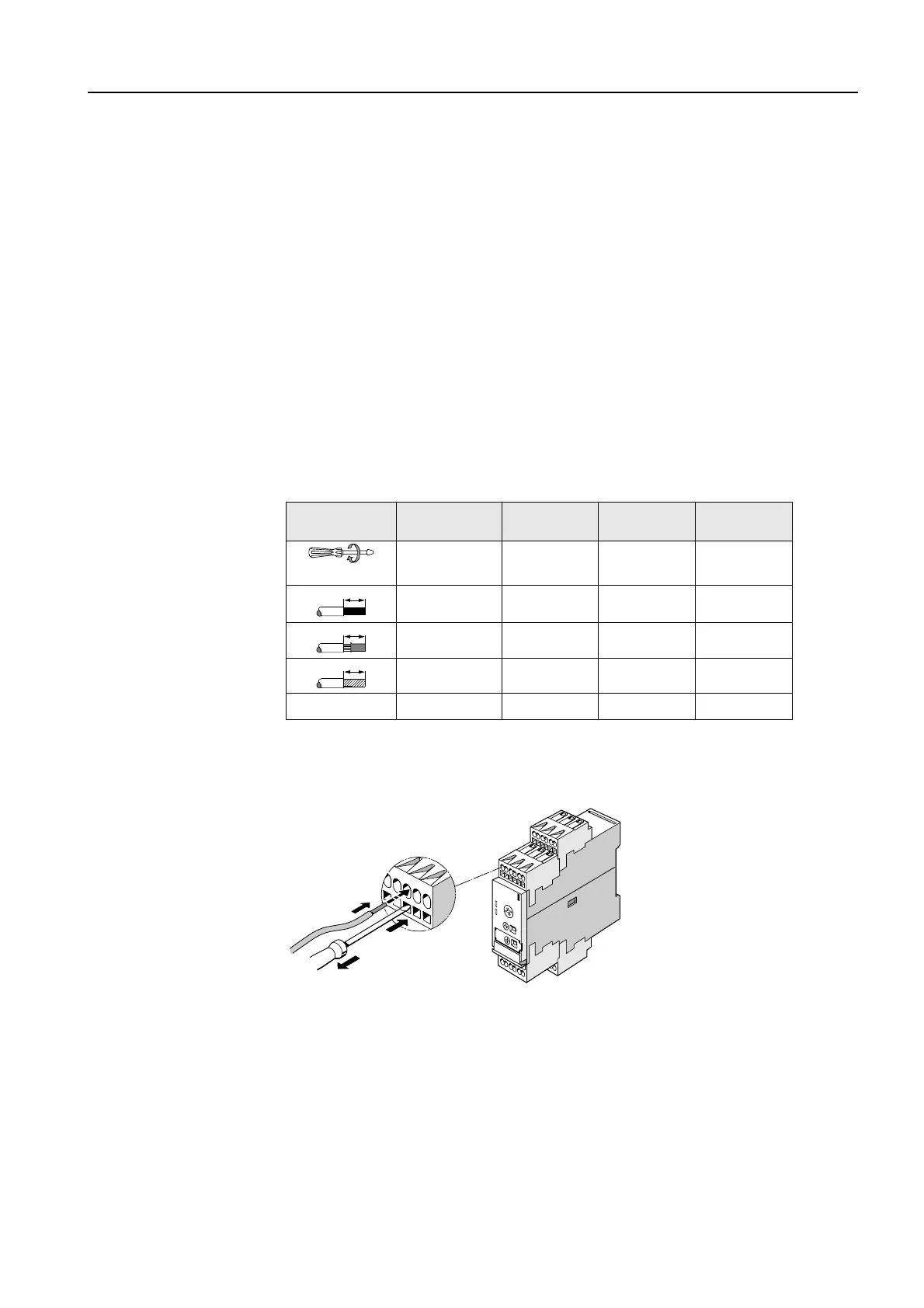
The following illustration shows you the Cage Clamp terminal:
Figure 7-20: Cage Clamp terminals
3RP10.0-1 3RP10.0-2
(Cage Clamp)
3RP15 3RP15..-2
(Cage Clamp)
∅
5 to 6 mm / PZ2
0.8 to 1.2 Nm
7 to 10.3 lb.in
------
0.8 to 1.2 Nm
7 to 10.3 lb.in
------
2 x (0.5 to 1.5 mm²)
2 x (0.75 to 4 mm²)
2 x (0.25 to 2.5 mm²) 1 x (0.5 to 4 mm²)
2 x (0.5 to 2.5 mm²)
2 x (0.25 to 1.5 mm²)
2 x (0.5 to 2.5 mm²) 2 x (0.25 to 1 mm²)
1 x (0.5 to 2.5 mm²)
2 x (0.5 to 1.5 mm²)
2 x (0.25 to 1 mm²)
------ 2 x (0.25 to 1.5 mm²) ------ 2 x (0.25 to 1.5 mm²)
AWG
2 x (18 to 14) 2 x (24 to 14) 2 x (20 to 14) 2 x (24 to 16)
10
10
10