3RP10, 3RP15 solid-state time relays
SIRIUS System Manual
GWA 4NEB 430 0999-02b
7-17
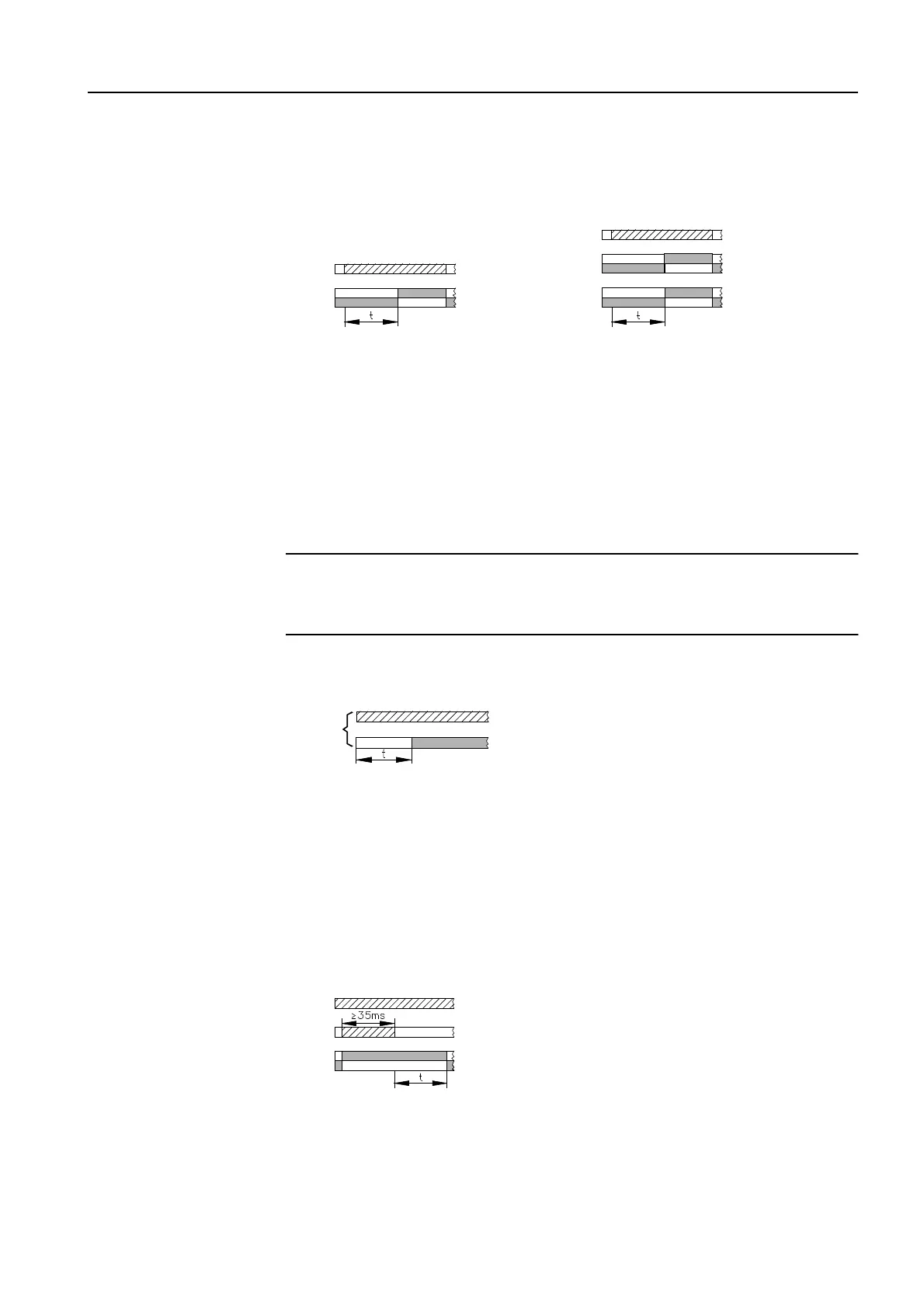
Function diagrams
The function diagram for the time relay with 1 changeover contact and with
2 changeover contacts:
Figure 7-9: 3RP15 25 function diagram
The 3RP15 27 solid-state time relay (two-wire time relay)
The two-wire time relay is connected in series with the load. The timing
period begins after the control supply voltage has been applied. The semi-
conductor output then becomes live, and voltage is applied to the load.
Time ranges
Four time ranges can be set by means of a rotary switch.
Important
Attention must be paid to the rated operational current, residual current with
unswitched output, and voltage drop in the case of a switched output.
Function diagram
Figure 7-10: 3RP15 27 function diagram
7.3.4 Off-delay
The 3RP15 31/32/33 solid-state time relay with auxiliary supply
The time relay contains 1 changeover contact.
Time ranges
Fixed time ranges are offered: 10 s, 30 s, 100 s
Function diagram
Figure 7-11: 3RP15 3. function diagram
There is continuous auxiliary voltage (A./A2) at the time relay. If a control
supply voltage is applied to the start contact, the output relay switches over.
After the start contact is disconnected, the set runtime starts. The minimum
on-time of
≥
35 ms must be adhered to.
On-delay
2 changeover contacts
1 changeover contact
On-delay
ON DELAY
A./A2
15/18
15/16
25/28
25/26
A./A2
15/18
15/16
ON DELAY
Off-delay
OFF DELAY
A./A2
B./A2
15/18
15/16