3RT1/3RH1 contactors
SIRIUS System Manual
GWA 4NEB 430 0999-02b
3-63
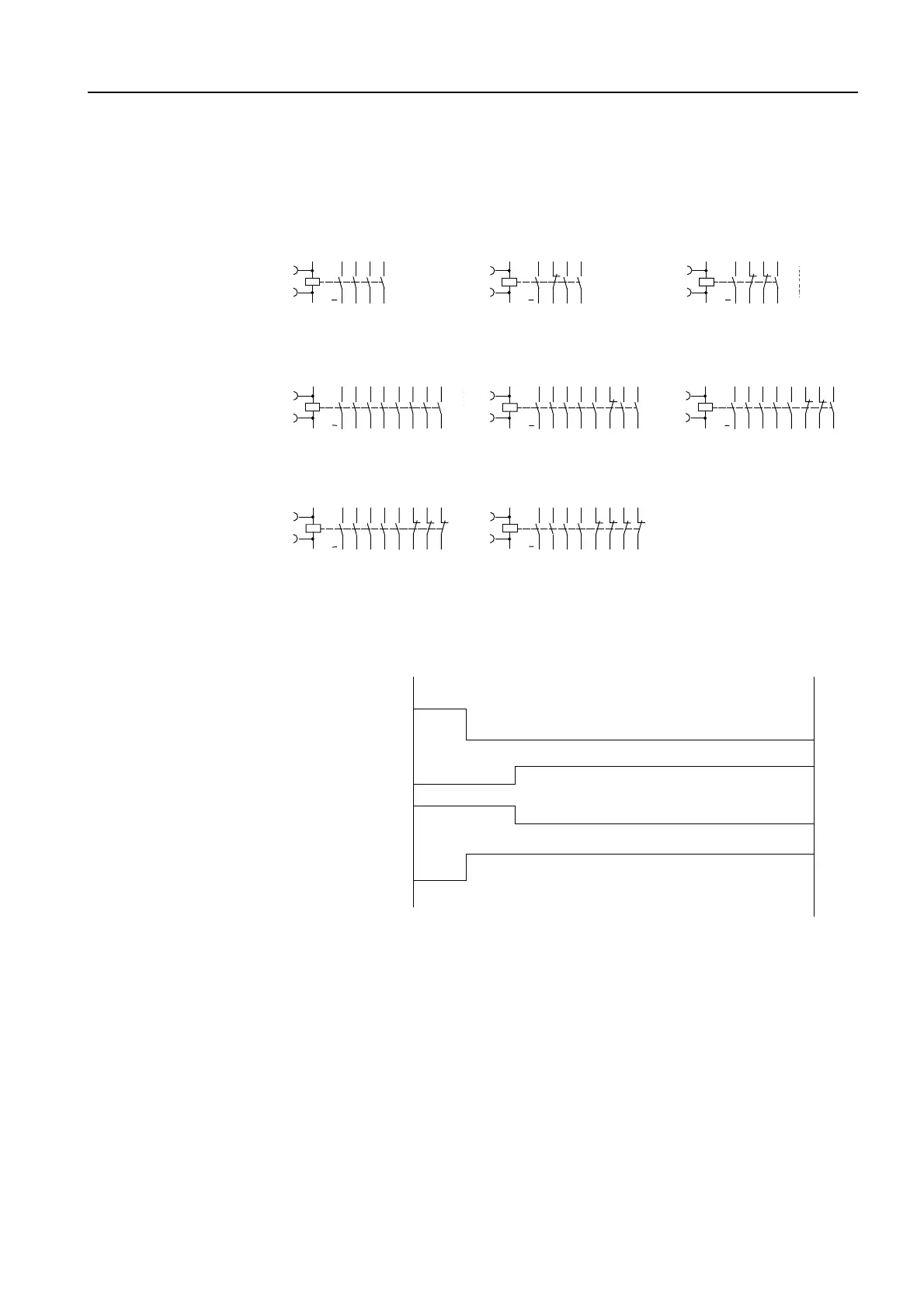
Device circuit diagrams
The following device circuit diagrams of the auxiliary contactors contain ter-
minal markings in acc. with EN 50 011:
Figure 3-40: Device circuit diagrams
Position diagrams
The following position diagrams of the auxiliary switches of frame sizes S00
to S3 also apply to leading and lagging contacts:
Figure 3-41: Position diagrams of the auxiliary switches (frame sizes S0 to S3)
13 23 33 43
44342414
A2( )
A1(+)
NS2-5552
13 21 33 43
44342214
A2( )
A1(+)
NS2-5553
13 21 31 43
44322214
A2( )
A1(+)
NS2-5554
4 NO contacts
Identification number: 40 E
3 NO contacts + 1 NC contact
Identification number: 31 E
2 NO + 2 NC contacts
Identification number: 22 E
8 S
Identification number: 80 E
7 NO contacts + 1 NC contact
Identification number: 71 E
6 NO + 2 NC contacts
Identification number: 62 E
5 NO + 3 NC contacts
Identification number: 53 E
4 NO + 4 NC contacts
Identification number: 44 E
13 23 33 43
44342414
A2( )
A1(+)
NS2-5558
53 63 73 83
84746454
13 23 33 43
44342414
A2( )
A1(+)
NS2-5559
53 61 73 83
84746254
13 23 33 43
44342414
A2( )
A1(+)
NS2-5560
53 61 71 83
84726254
13 23 33 43
44342414
A2( )
A1(+)
NS2-5561
53 61 71 81
82726254
13 23 33 43
44342414
A2( )
A1(+)
NS2-5562
51 61 71 81
82726252
N
S
N
S
On
Off
On
Off
On
Off
On
Off
Standard
auxiliary
switch
Overlapping
auxiliary
switches