3RV1 circuit breaker
SIRIUS System Manual
GWA 4NEB 430 0999-02b
2-53
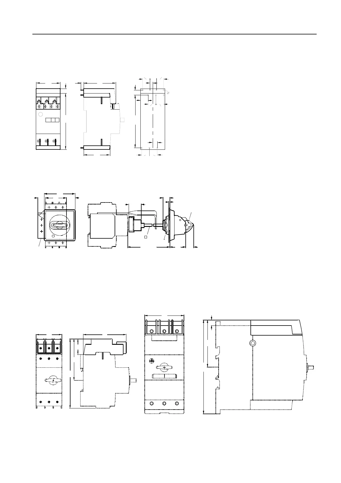
Soldering pin connector for main and auxiliary switches
Figure 2-48: 3RV19 18-5A/-5B (frame size S00)
Rotary switch extension for the door
Figure 2-49: 3RV19 26-0 (frame sizes S0, S2, S3)
1) Lockable in 0 position with shackle (max. 8 mm in diameter)
2) Affixed with screw caps
5) Ground terminal 35 mm
2
and support bracket for 330 mm shaft
Terminals for "Combination Motor Controller Type E" in acc. with UL 508
Figure 2-50: 3RV19 28-1H (frame size S0) and 3RT19 46-4GA07 (frame size S3)
45
NSB00041
13.4
12
13.1
5
8.4
14.4 14.4
8.4
14.4
14.4
97.4
9
103
9
59
49
5
2
NSB 01090b
16
5
min. 55
2
1
5
45
66
19
15
1 ... 4
17
33
max. 327
34.5
27
72
121
7445
NSB 01228
10
NSB 01229
168
70
84