3RT1/3RH1 contactors
SIRIUS System Manual
GWA 4NEB 430 0999-02b
3-69
Function diagrams
3RT1916-2C, on-delay 3RT1916-2D, off-delay
Figure 3-48: Solid-state time relay block with semiconductor output, function diagrams (frame size
S00)
Circuit diagrams
3RT1916-2C 3RT1916-2D
on-delay off-delay with auxiliary supply
Figure 3-49: Solid-state time relay with semiconductor output, circuit diagrams (frame size S00)
3.4.3.2 Frame size S0 to S3 (3RT1926-2C, -2D)
Note on configuration
Caution
The solid-state time relay block with a semiconductor output
(3RT1926-2C, -2D) must not be used for 3RT104 contactors of frame size S3
with U
S
≤
42 V because the coil current used for the output semiconductor
is too high.
The solid-state time relay block must not be attached to the lower coil con-
nections.
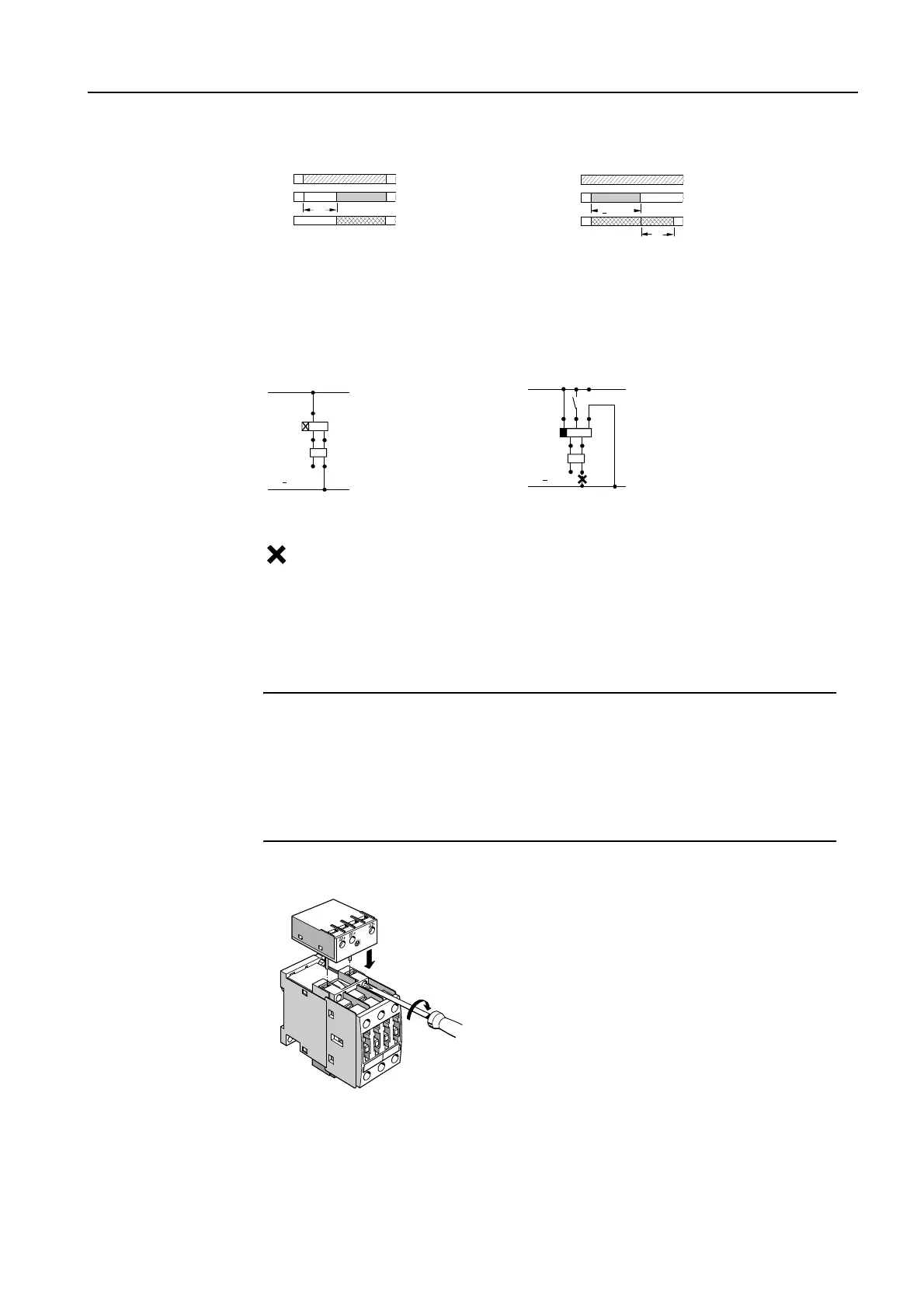
Installation/removal
Figure 3-50: Solid-state time relay with a semiconductor output, installation (frame size S00)
NSK-7937a
A1/A2
A1/A2
t
Time relay
Contactor
NSK-7938a
A1/A2
A1/A2
B1/A2
35 ms
>
t
Time relay
Contactor
K1 Solid-state time relay block
K2 Contactor
Connection prohibited!
N/L
L1/L+
A2
A2
A1
A1
A1
K1
K2
L1/L+
S1
A2
A1 B1
A2
A2
A1
A1
K2
K1
The solid-state time relay block
for the contactors of frame sizes
S0 to S3 is attached at the top on
the A1 and A2 coil connections
of each contactor, connecting the
time relay electrically and mecha-
nically with pins.
2
1