3RP10, 3RP15 solid-state time relays
SIRIUS System Manual
GWA 4NEB 430 0999-02b
7-15
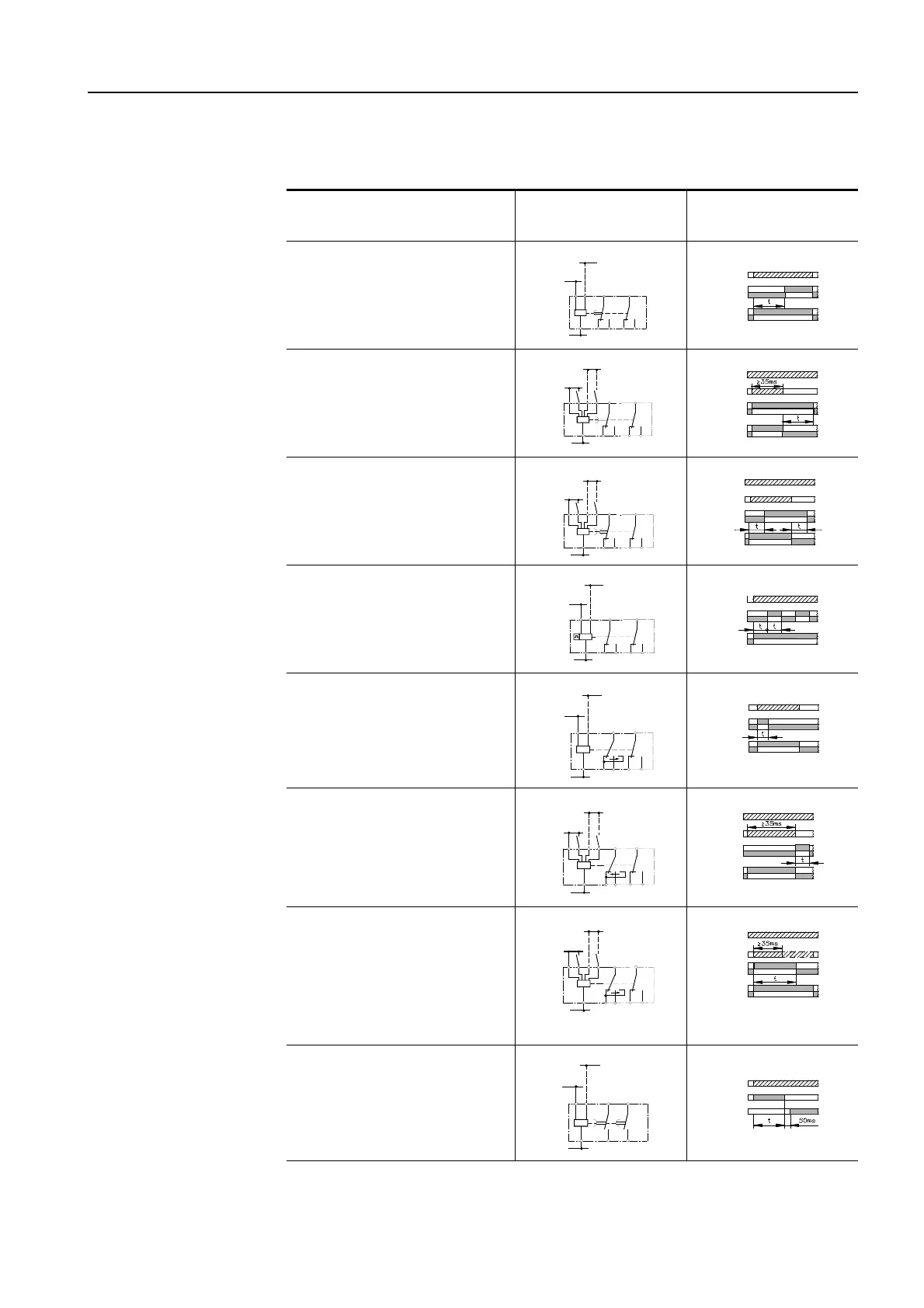
Table continued: Function diagrams (3RP15)
Table 7-5: Function diagrams and circuit diagrams
Identifying letter
Device circuit
diagrams
Function diagram
A
•
On-delay and immediate
switching
B
•
Off-delay with auxiliary sup-
ply and immediate switch-
ing
C
•
On-delay and off-delay with
auxiliary supply and imme-
diate switching
(t=t
on
=t
off
)
D
•
Flashing, start with break
(pulse/break 1:1) and imme-
diate switching
E
•
Making pulse contact and
immediate switching
F
•
Breaking pulse contact with
auxiliary supply and imme-
diate switching
G
•
Shaping pulse contact with
auxiliary supply and imme-
diate switching
(creates a pulse at the out-
put irrespective of the dura-
tion of excitation)
*d
Star-delta function
* Only with devices with 2 changeover contacts
A3
15
A2 1816
A1
AC/DC24V
AC100/12 7V
AC200/24 0V
21
24
NSB00917
22
A./A2
15/18
15/16
21/24
21/22
NSB009 18
AC/DC24V
AC100/127V
AC200/240V
A1 15
A2
16
A3B1 B3
18
21
24
22
21/24
21/22
A./A2
B./A2
15/18
15/16
NSB00919
AC/DC24V
AC100/127V
AC200/240V
A1 15
A2 16
A3B1 B3
18
21
24
22
21/24
21/22
A./A2
B./A2
15/18
15/16
A3 15
A2 18
16
A1
AC/DC24V
AC100/127V
AC200/240V
21
24
NSB0 0920
22
~
A./A2
21/24
21/22
15/18
15/16
A3 15
A2 18
NSB00921
16
A1
AC/DC24V
AC100/127V
AC200/240V
21
24
22
A./A2
15/18
15/16
21/24
21/22
NSB00922
AC/DC24V
AC100/127V
AC200/240V
A1
A2
A3B1 B3 15
1816
21
2422
21/24
21/22
A./A2
B./A2
15/18
15/16
NSB00923
AC/DC24V
AC100/127V
AC200/240V
A1
A2
A3B1 B3
15
1816
21
24
22
21/24
21/22
A./A2
B./A2
15/18
15/16
A3
Y18
A2
NSB00924
17
A1
AC/DC24V
AC100/127V
AC200/240V
d
28
27
A./A2
17/18
27/28