3RV1 circuit breaker
SIRIUS System Manual
GWA 4NEB 430 0999-02b
2-49
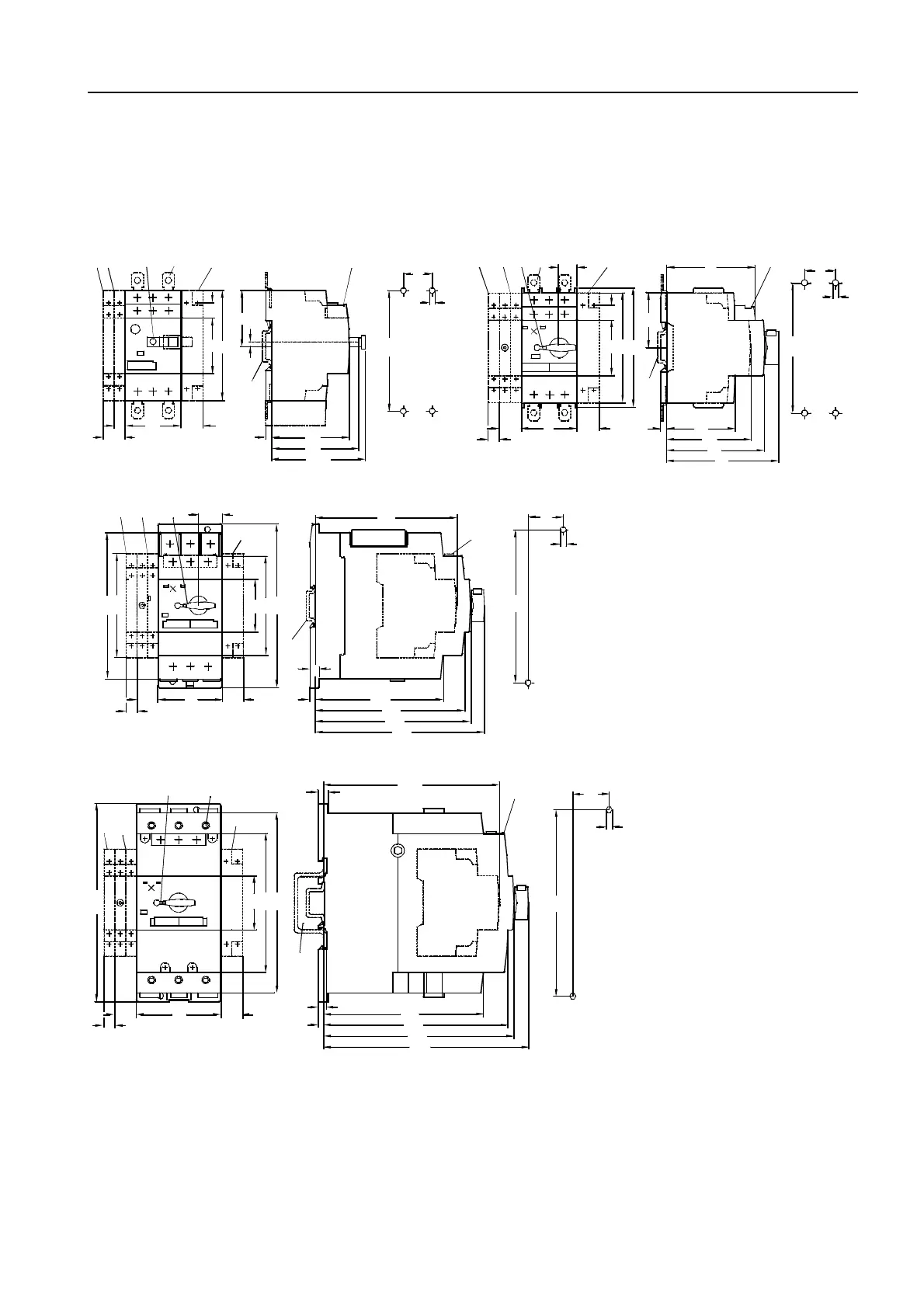
2.6 Dimensioned drawings
(measurements in mm)
3RV1 circuit breakers
Figure 2-37: 3RV10 11, 3RV16 (frame size S00) 3RV10 21 (frame size S0)
Figure 2-38: 3RV10 31 (frame size S2)
Figure 2-39: 3RV10 4 (frame size S3)
1) Lateral auxiliary switch, 2-pole 7) Drilling pattern
2) Alarm switch (S0 to S3) or lateral auxiliary switch, 4-pole (S00 to S3) 8), 35 mm rail in acc. with EN 50022
3) Auxiliary release 9)
Mounting onto 35 mm rail, 15 mm high, in acc. with EN 50 022
4) Transverse auxiliary switch or 75 mm rail in acc. with EN 50023
5) Push-in lugs for screw mounting 10) 4 mm Allen screw
6) Only with undervoltage release with leading auxiliary switch 11) Lockable in 0 position with shackle (5 mm in diameter)
1
11
3
4
5
8
NSB 00026c
45
90
70
76
9 18
62
5
45
12
45
3,5
6
2
18
25
5
105
7
11
2
5
4
8
3
1
NSB00027b
45
14
12
90
97
45
5
56
80
91
45
69
18 18
72
9
5
25
106
7
20
5518 18
45
85
109
121
127
5
8
132
144
140
89
125
1
2
3
4
8
NSB00028a
11
9
5
30
130
7
45
7018 18
116
165
150
5
7
8
132
153
157
146
10
11
1
2
3
4
9
NSB00029b
169
9
5
30
155
7