3RW3 semiconductor motor control unit
SIRIUS System Manual
GWA 4NEB 430 0999-02b
8-33
Diagnostics
Table 8-15: 3RW30/31 diagnostics
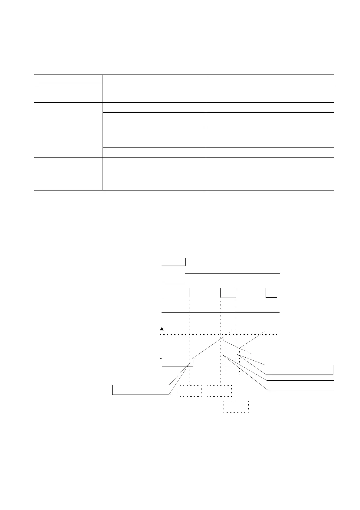
8.3.7 Timing diagram
Starting and coasting-
down behavior
The following timing diagram shows the switchover times when the device
is switched on/off:
Figure 8-17: Starting and coasting-down behavior
Malfunction Possible cause Remedy
READY LED off • Supply voltage too low
• Check and adapt the supply
voltage at A1, A2
No reaction to con-
trol input IN
(READY LED on)
• No supply voltage • Check fuses/line contactor
• Phase loss
• Check fuses/line contactor
• Check voltages at L1 to L3
• Wrong cable connected to IN
• Connect to IN as shown in the graphic
of the terminals
• No load • Connect the motor
Start the motor
directly
(BYPASSED LED on)
• The line voltage is switched off
and on in continuous operation
without operation of the con-
trol input IN
• Always switch the line contactor off and
on in conjunction with control input IN
L1-L2-L3
A1-A2
IN
Bypass
T1-T2-T3
U
U
N
S
On-delay approx. 80 ms
ON
command
OFF
command
ON
command
Switchover delay approx. 30 ms
Switchover delay approx. 30 ms
Switchover delay approx. 30 ms