3RT1/3RH1 contactors
SIRIUS System Manual
GWA 4NEB 430 0999-02b
3-17
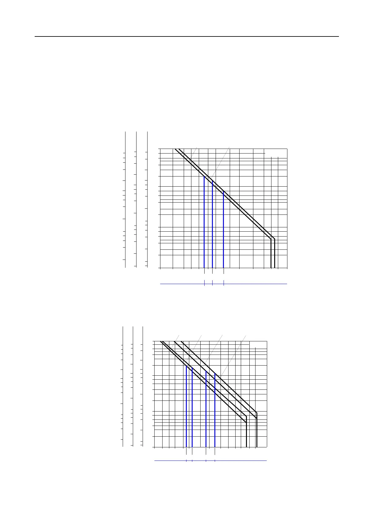
Characteristic curve:
contact service life of
the main contacts
The characteristic curves illustrate the contact service life of the main con-
tacts of contactors when switching inductive three-phase loads (AC-3).
I
a
= breaking current
I
e
= rated operational current
P
N
=
rated output of three-phase induction motors with squirrel cage at
400 V
Frame size S00
Figure 3-3: Characteristic curve of the electrical service life of the main contacts (frame size S00)
Frame size S0
Figure 3-4: Characteristic curve of the electrical service life of the main contacts (frame size S0)
10
8
6
4
2
10
8
6
4
2
10
8
6
4
2
10
7
6
5
4
6
4
2
10
8
6
4
2
10
8
6
4
2
10
8
6
5
4
8
6
4
2
10
8
6
4
2
10
8
6
4
2
10
6
5
4
10
8
6
4
2
10
8
6
4
2
10
8
6
4
2
7
6
5
2
3 4 5 8 10 20 50 60 80
912
40
NSB00473a
4
I
(A)
a
I
(A)
e
P
(kW)
N
7
3
6
5,5
3RT1015
(3 kW)
3RT1016, 3RT1017
(4 kW, 5,5 kW)
690 V
500 V
230 V
400 V
Contactor type
Operating cycles at
12 17
3RT1024
25
3RT1025
3RT1026
11
P
N
(11 kW)
10 20 30 40 50 60 80 100
(A)
I
I
e
(A)
(kW)
(5,5 kW) (7,5 kW)
34
5
68
9
4
3RT1023
(4 kW)
NSB00474a
10
8
6
4
2
10
8
6
4
2
10
8
6
4
2
7
6
5
4
6
4
2
10
8
6
4
2
10
8
6
4
2
10
8
6
5
4
8
6
4
2
10
8
6
4
2
10
8
6
4
2
10
6
5
4
10
8
6
4
2
10
8
6
4
2
10
8
6
4
2
7
6
5
690 V
500 V
230 V
400 V
10
Contactor type
5,5 7,5
Operating cycles at
 Loading...


