3RT1/3RH1 contactors
SIRIUS System Manual
3-88
GWA 4NEB 430 0999-02b
Vertical installation
position
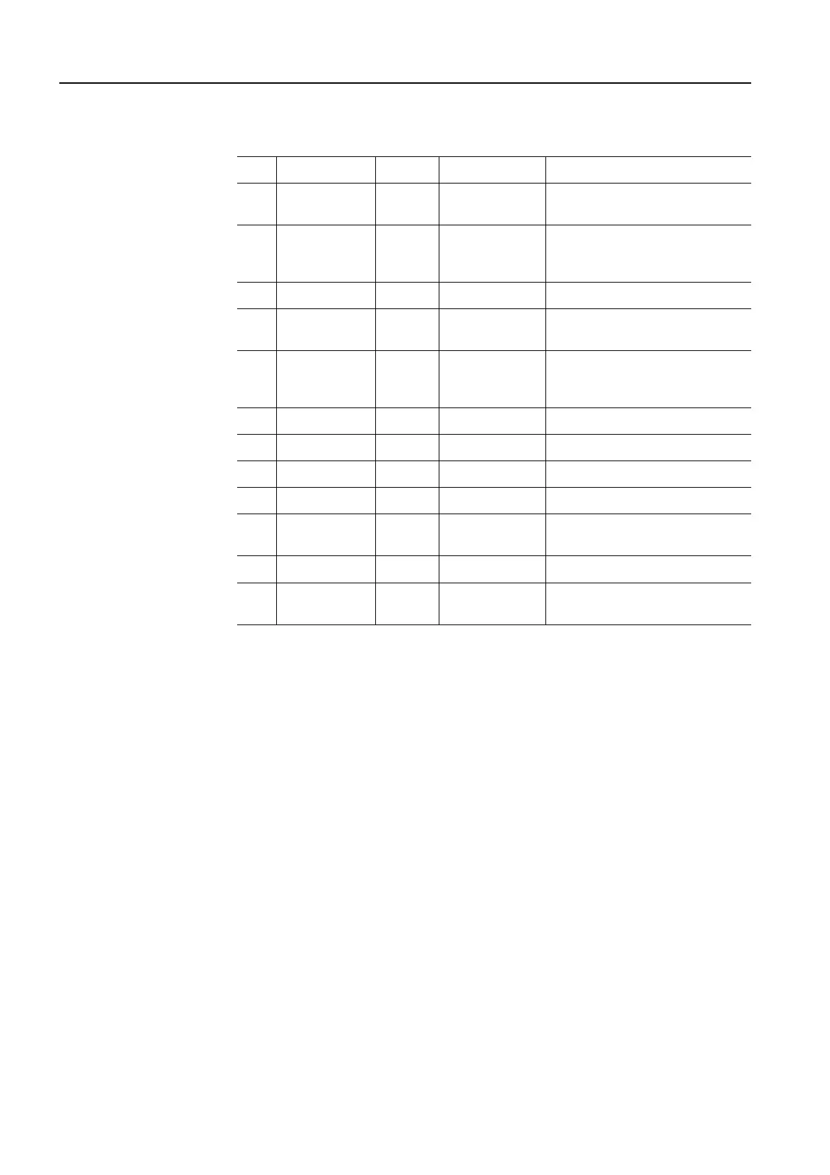
The following table indicates usage in a vertical installation position:
Table 3-35: Vertical installation position
Motor and auxiliary contacts (including the contactor relay variants) are
included in frame size S00.
Installation in series
No derating is necessary up to an ambient temperature of 60 °C for all the
contactors, even those in side-by-side installation.
In the case of contactors with an extended operating range (0.7 to 1.25 x U
s
)
that use a series resistor, installation in series is permissible up to an ambi-
ent temperature of +70 °C.
3.5.2 Connection
The SIRIUS contactors are available with the following terminal types:
• Frame sizes S00 to S3: screw-type terminals
• Contactors and auxiliary contactors of frame size S00: All the terminals
are also available as Cage Clamp terminals
• Contactors of frame sizes S0 to S3: The auxiliary switches and coil con-
nections are also available with Cage Clamp terminals.
• Accessories: screw-type and (for most of the range) Cage Clamp termi-
nals
• The contactors of frame size S3 have removable box terminals for the
main conductor terminals. This enables the connection of ring lugs or bus-
bars.
No. Size AC/DC Output power Measure
1 S00 coupler
3RT10 1.
DC 3 to 5.5 kW Without restriction
1 S00 coupler
3RH11
DC I
e
/AC-15
6 A/230 V
With 2 NO + 2 NC contacts:
stronger springs,
otherwise no restriction
2 S00 3RT10 1. DC 3 to 5.5 kW Without restriction
2S00 3RH11 DC I
e
/AC-15
6 A/230 V
Without restriction
3 S00 AC 3 to 5.5 kW/
and I
e
/AC-15
6 A/230 V
Special variant
4 S0 coupler DC 5.5 to 11 kW Special variant
5 S0 DC 4 to 11 kW Special variant
6 S0 AC 4 to 11 kW Without restriction
8 S2 AC 15 to 22 kW Special variant
9 S2 DC 15 to 22 kW Vertical installation position not
possible.
10 S3 AC 30 to 45 kW Special variant
11 S3 DC 30 to 45 kW Vertical installation position not
possible.